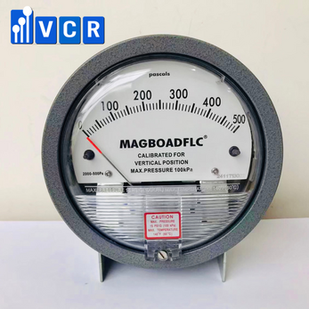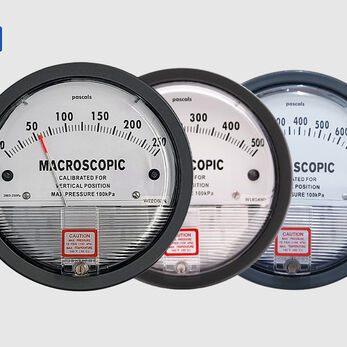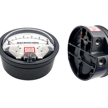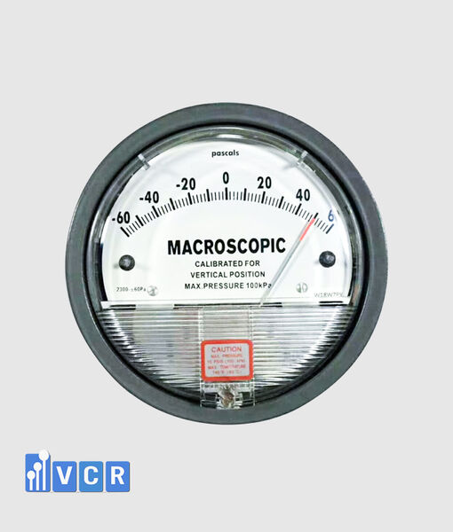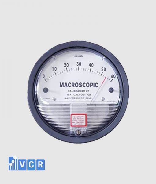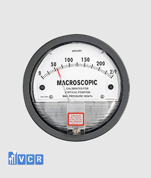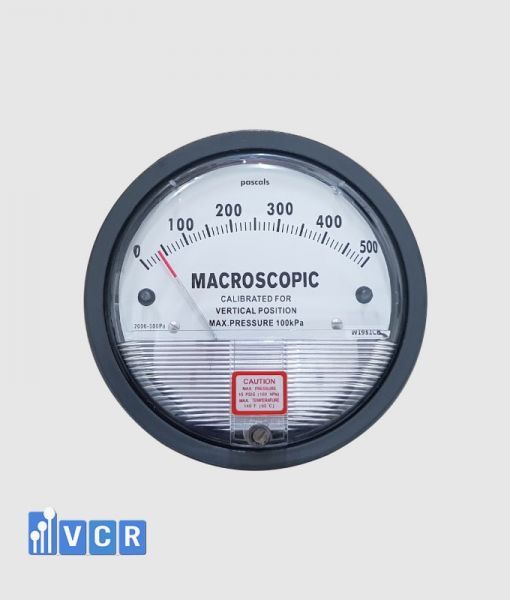

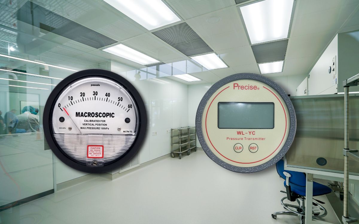
Mechanical differential pressure gauges offer simple local indication without an external power supply. Electronic gauges provide configurable alarms, signal transmission, data logging and integration with cleanroom control systems.
- What are mechanical and electronic differential pressure gauges?
- What do the two types have in common?
- How does a mechanical differential pressure gauge work?
- How does an electronic differential pressure gauge work?
- Comparison table
- Display and readability
- Accuracy and resolution
- Power supply requirements
- Alarm capability
- Signal transmission
- PLC, HMI and BMS integration
- Data logging
- Reliability
- Installation requirements
- Calibration and functional testing
- Cost comparison
- When should a mechanical gauge be selected?
- When should an electronic gauge be selected?
- Should both types be used together?
- Common selection mistakes
- Frequently asked questions
- Conclusion
What are mechanical and electronic differential pressure gauges?
A differential pressure gauge measures the pressure difference between two locations. In cleanroom and HVAC applications, it is commonly used to monitor room pressure or measure pressure drop across pre-filters, bag filters, HEPA filters and other air-handling components.
The two common categories are mechanical differential pressure gauges and electronic differential pressure gauges. Both measure the same physical parameter, but they differ in sensing technology, display method, alarm capability, communication and integration with control systems.
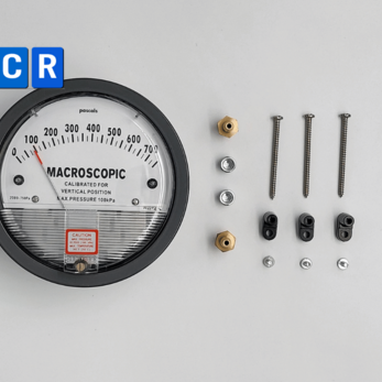
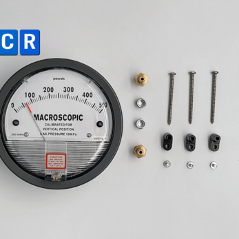
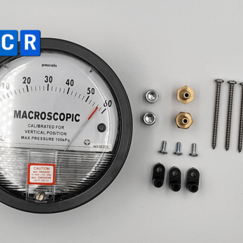
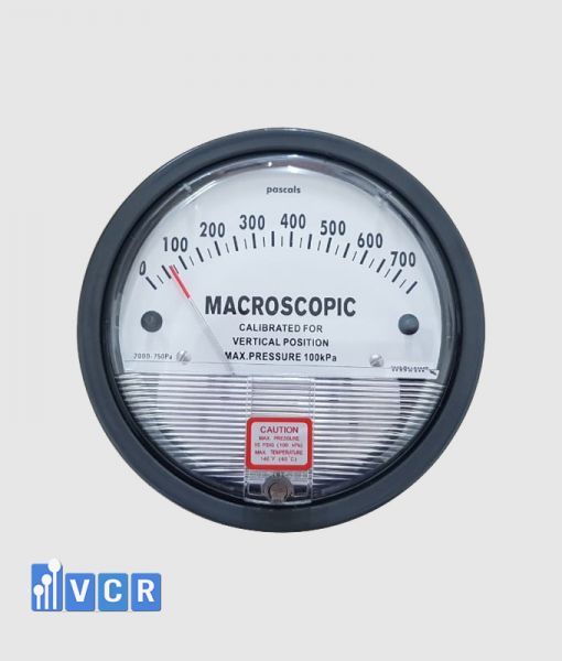
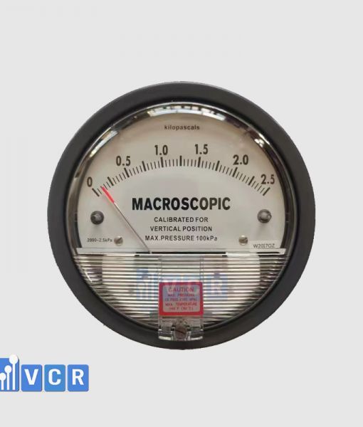
A mechanical differential pressure gauge, also called an analogue DP gauge or needle-type differential pressure gauge, displays the measured value with a pointer moving across a graduated dial.
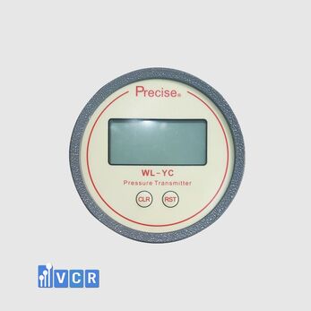
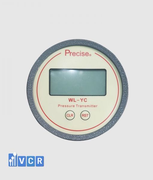
An electronic differential pressure gauge uses a pressure sensor and signal-processing circuit to convert the pressure difference into a digital value. The measurement can be displayed locally and transmitted to a PLC, HMI, BMS or environmental monitoring system.
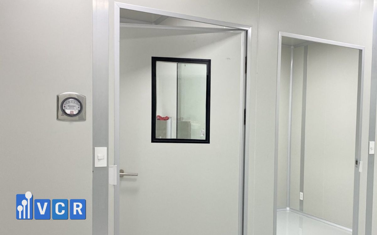
What do the two types have in common?
Both mechanical and electronic gauges normally have two pressure ports:
-
High, Positive or “+” port.
-
Low, Negative or “−” port.
The measurement is calculated as:
Differential pressure = High-port pressure − Low-port pressure
For room-pressure monitoring, the High port is connected to the space with the higher design pressure, while the Low port is connected to the lower-pressure space.
For filter monitoring, the High port is connected upstream of the filter and the Low port downstream. As dust loading increases filter resistance, differential pressure normally increases when airflow remains similar.
Both technologies may be used for:
-
Cleanrooms.
-
AHUs.
-
HEPA boxes.
-
Dynamic pass boxes.
-
Air showers.
-
Fan filter units.
-
Laminar airflow units.
-
Dispensing booths.
-
Sampling booths.
-
HVAC systems.
-
Pre-filters, bag filters and HEPA filters.
The main difference is how the measured value is processed, displayed and used.
How does a mechanical differential pressure gauge work?
A mechanical gauge uses a diaphragm, capsule, flexible membrane or magnetic mechanism to sense the pressure difference.
When the pressures at the two ports are different, the sensing element deflects or moves. This movement is transmitted through a mechanical or magnetic mechanism to the pointer.
The pointer moves to the corresponding position on the graduated scale.
Most mechanical gauges do not require an external power supply. They provide direct local indication and are suitable for points where operators only need to observe the value at the installation location.
How does an electronic differential pressure gauge work?
An electronic gauge uses a differential pressure sensor to convert pressure into an electrical signal.
Internal electronics amplify, compensate, linearise and convert this signal into a digital value. Depending on the model, the instrument may provide:
-
LCD or LED display.
-
4–20 mA output.
-
0–10 V output.
-
Relay contacts.
-
RS485 communication.
-
Modbus RTU or Modbus TCP.
-
Audible or visual alarms.
-
Data logging or remote transmission.
-
Multiple configurable alarm levels.
Electronic gauges can therefore become part of an automatic monitoring and control system.
Comparison table
| Criterion | Mechanical gauge | Electronic gauge |
|---|---|---|
| Display | Analogue pointer and scale | Digital display |
| Power supply | Normally not required | Required |
| Local visibility | Good | Good |
| Resolution | Based on scale divisions | Usually higher |
| Reading error | Parallax may occur | Minimal parallax |
| Signal output | Normally unavailable | 4–20 mA, 0–10 V, RS485 or Modbus |
| Alarm functions | Limited | Flexible |
| Data logging | Not available | May be integrated |
| PLC/HMI/BMS connection | Limited | Suitable |
| Automatic control | Not suitable without a transmitter | Suitable |
| Initial cost | Usually lower | Usually higher |
| Electrical installation | Simple | Power and signal wiring required |
| Configuration | Normally unnecessary | May require programming |
| Maintenance | Relatively simple | Includes sensor and electronic checks |
| Operation during power loss | Indication remains if pressure exists | Requires backup power |
Display and readability
A mechanical pointer allows operators to see whether the pressure is rising or falling. Coloured zones or adjustable markers can make normal and abnormal conditions easy to recognise.
However, the reading can be affected by the viewing angle. Looking at the dial from the side may create parallax error. Resolution is also limited by the spacing between scale divisions.
An electronic gauge displays a numerical value, reducing the need to estimate between scale marks. Some instruments also display the measurement unit, alarm status and operating trend.
Digital displays still depend on power and may be difficult to read if brightness, viewing angle or ambient lighting is unsuitable.
Accuracy and resolution
Accuracy is not determined only by whether a gauge is mechanical or electronic. It depends on the model, measuring range, sensing technology, manufacturing quality and calibration condition.
Electronic gauges often provide higher display resolution because they can show individual pascals or decimal values. However, more digits on the display do not automatically mean better measurement accuracy.
Mechanical gauges can also provide reliable accuracy when the measuring range is selected correctly and the instrument is properly installed and calibrated. Their main limitation is the ability of an operator to estimate the value between scale marks.
Selection should consider:
-
Permissible error.
-
Full-scale or reading-based accuracy.
-
Repeatability.
-
Hysteresis.
-
Temperature influence.
-
Zero stability.
-
Calibration interval.
-
Working range and overpressure limit.
Power supply requirements
A standard mechanical gauge does not normally require electrical power. This is useful for local monitoring and for maintaining an independent indication when the control system is unavailable.
The gauge still requires an actual pressure difference. If the entire facility loses power and the fan stops, room or filter differential pressure will normally fall toward zero.
An electronic gauge requires a supply such as 24 VDC or 24 VAC, depending on the model. If the supply is lost, the display and output signal may stop.
For critical points, the gauge, PLC, HMI and monitoring system may need to be connected to a UPS.
Alarm capability
Most mechanical gauges only provide visual indication. An operator must inspect the gauge to detect an out-of-limit condition.
Certain mechanical models include electrical contacts or adjustable setpoint pointers. Their configuration is generally less flexible than that of an electronic device.
Electronic gauges may support:
-
Low alarm.
-
High alarm.
-
Low-low alarm.
-
High-high alarm.
-
Alarm delay.
-
Hysteresis.
-
Automatic reset.
-
Latched alarm requiring acknowledgement.
-
Normally open or normally closed relays.
These functions are valuable in pharmaceutical cleanrooms, isolation rooms, dispensing booths, negative-pressure rooms and other critical areas.
Signal transmission
A basic mechanical gauge does not provide an electrical output. Remote transmission requires an additional transmitter or a gauge with an integrated electrical output.
Electronic gauges may provide 4–20 mA or 0–10 V analogue signals.
A 4–20 mA signal is commonly used for industrial transmission because it is relatively resistant to electrical interference and suitable for longer cable distances. Four milliamps normally represents the lower end of the range, while 20 milliamps represents the upper end.
RS485 and Modbus communication can transmit measurement values, alarm states, configuration parameters and diagnostic information over a communication network.
Multiple instruments may share one bus, reducing the number of individual analogue signal cables in large installations.
PLC, HMI and BMS integration
A mechanical gauge is suitable for an independent local indication where data transmission is not required. Operators read and record the value according to an inspection schedule.
An electronic gauge is more suitable when the value must be displayed on an HMI, stored on a server or used in control logic.
A PLC can use the signal to:
-
Generate alarms.
-
Control fan speed through a variable-frequency drive.
-
Display values on the HMI.
-
Store pressure history.
-
Generate trend graphs.
-
Activate warning lights and buzzers.
-
Transmit information to a BMS.
-
Operate interlocks.
Using differential pressure for automatic control requires properly designed logic. The system should include alarm delays, output limits, fault detection and protection against control oscillation.
Data logging
A mechanical gauge does not automatically store historical data. Operators must manually record readings in paper forms, spreadsheets or maintenance software.
Manual recording may result in:
-
Missing data.
-
Transcription errors.
-
Incorrect timestamps.
-
Limited trend analysis.
-
Difficulty identifying when a fault began.
Electronic gauges can transmit measurements continuously to a PLC, BMS or monitoring system. Historical data helps operators evaluate filter loading, room-pressure stability and HVAC performance.
For GMP applications, electronic records may require access control, timestamps, audit trails, backup, security and data-integrity controls.
Reliability
Mechanical gauges have relatively simple construction and are not dependent on electrical power, software or communication networks. They are useful as independent local indicators.
However, mechanical elements may be affected by vibration, shock, ageing, incorrect installation orientation and zero drift.
Electronic gauges eliminate the pointer mechanism but depend on the sensor, power supply, electronic circuit, configuration and signal network.
Possible electronic faults include:
-
Power failure.
-
Broken signal wiring.
-
Electrical interference.
-
Incorrect range configuration.
-
Communication failure.
-
Display failure.
-
Sensor zero drift.
For critical measurement points, a mechanical local gauge may be installed together with an electronic transmitter. This provides an independent value for comparison.
Installation requirements
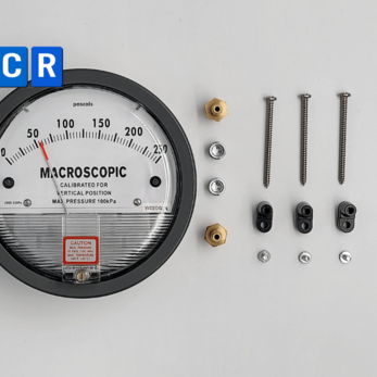
A mechanical gauge normally requires the instrument body, two pressure tubes and pressure tapping accessories. Installation is relatively straightforward.
An electronic gauge additionally requires:
-
Power wiring.
-
Signal cables.
-
Control panel or junction box.
-
Range configuration.
-
Unit selection.
-
Relay configuration.
-
Communication addressing.
-
PLC or BMS programming.
For both types, pressure tubing remains critical. Leaks, kinks, blockages and condensation can cause incorrect readings regardless of the sensing technology.
Calibration and functional testing
Both technologies should be tested against a reference differential pressure source when the measurement point is included in the facility’s quality system.
Mechanical gauge testing should cover:
-
Zero position.
-
Accuracy at several scale points.
-
Repeatability.
-
Return to zero.
-
Pointer and dial condition.
Electronic gauge testing should additionally verify:
-
4–20 mA or 0–10 V output.
-
Alarm relays.
-
Alarm delay.
-
HMI value.
-
Modbus communication.
-
Range configuration.
-
Response to signal or sensor failure.
Zero adjustment does not replace calibration. Calibration verifies accuracy at multiple values using a suitable reference instrument.
Cost comparison
Mechanical gauges normally have a lower purchase and installation cost. They do not require power wiring, signal modules or control programming.
Electronic gauges generally have a higher initial cost because they include sensors, displays, signal-processing electronics and communication functions.
The total installed cost may also include:
-
Electrical cables.
-
Control panels.
-
PLC input modules.
-
HMI programming.
-
Data-storage systems.
-
Signal testing.
-
Calibration and software qualification.
Electronic monitoring may reduce manual inspection, support predictive maintenance and detect faults earlier. The decision should therefore consider lifecycle cost rather than only purchase price.
When should a mechanical gauge be selected?
A mechanical gauge is normally suitable when:
-
Only local indication is required.
-
Remote transmission is unnecessary.
-
Automatic alarms are not required.
-
Continuous data storage is not needed.
-
The point is not used for automatic control.
-
The project has a limited budget.
-
Independence from electrical power is preferred.
-
A simple backup indication is required.
Typical applications include local monitoring of AHU filters, HEPA filters, HEPA boxes, pass boxes, air showers and non-critical room-pressure points.
When should an electronic gauge be selected?
An electronic gauge is normally preferred when:
-
Automatic alarms are required.
-
A 4–20 mA or 0–10 V signal is needed.
-
The device must connect to a PLC, HMI or BMS.
-
Historical data and trends are required.
-
Remote monitoring is required.
-
Multiple alarm levels are needed.
-
Fan or damper control is required.
-
The measurement point is critical.
-
Continuous records are required.
-
Event traceability is important.
Electronic gauges are especially useful in GMP cleanrooms, dispensing booths, isolation rooms, negative-pressure rooms, microbiology laboratories and central environmental monitoring systems.
Should both types be used together?
Combining a mechanical gauge with an electronic transmitter can be a practical approach.
The mechanical gauge provides direct local indication. The electronic transmitter sends data to the control system for alarm generation, trending and central monitoring.
This configuration provides several advantages:
-
Two values can be cross-checked.
-
Local indication remains available if the HMI fails.
-
Maintenance work becomes easier.
-
Display and control functions are separated.
-
Signal-network faults are easier to identify.
Both instruments should use suitable pressure tapping arrangements and should be calibrated to prevent confusing differences between readings.
Common selection mistakes
Buying an electronic gauge without using its outputs
If the project only requires local observation, purchasing communication and alarm functions may increase cost without providing practical value.
Using a mechanical gauge where continuous alarms are required
A basic pointer gauge cannot automatically notify operators. A fault may be missed if nobody is present at the location.
Selecting an excessively wide range
An unnecessarily wide measuring range reduces the visibility of small changes, especially for cleanroom room pressure.
Confusing resolution with accuracy
A display with many digits does not guarantee a low measurement error. The accuracy specification must be reviewed.
Ignoring power-loss conditions
An electronic gauge may stop displaying during a power failure. Critical points may require UPS power or a mechanical backup indicator.
Failing to test the complete signal chain
Electronic gauge commissioning should include the output signal, relay, HMI, alarm message and stored data rather than only the local display.
Frequently asked questions
Is an electronic gauge always more accurate?
No. Electronic instruments often have better display resolution, but actual accuracy depends on the model, range, sensing technology and calibration condition.
Can a mechanical gauge connect to a PLC?
A basic mechanical gauge cannot connect directly. A model with a transmitter or electrical contacts may be used, or a separate electronic transmitter can be installed.
What is the benefit of a 4–20 mA signal?
A 4–20 mA signal is suitable for industrial transmission, provides relatively good resistance to interference and allows a PLC to detect certain wiring or signal failures.
Is Modbus better than 4–20 mA?
Modbus can transmit more information over one network, while 4–20 mA is simpler and often easier to test. The correct choice depends on the system architecture and maintenance capability.
Which type should be used in a GMP cleanroom?
Mechanical gauges may be used for local indication. Electronic gauges are preferred when alarms, data logging or central monitoring are required. Many projects use both technologies.
Which type has lower maintenance costs?
Mechanical gauges are normally simpler, but they still require zero checks and calibration. Electronic gauges require additional checks of the power supply, outputs, relays and communication.
Conclusion
Mechanical differential pressure gauges provide simple, visible and cost-effective local indication. They normally operate without an external power supply and are suitable for non-automated monitoring points.
Electronic differential pressure gauges provide better alarm flexibility, signal transmission, data logging and integration with PLC, HMI and BMS systems. They are suitable for continuous monitoring and automatic control.
The selection should not be based only on purchase price or the assumption that electronic instruments are always superior. It should consider the measuring purpose, pressure range, alarm requirements, data-recording needs, point criticality and control-system architecture.
VCR Cleanroom Equipment supplies mechanical and electronic differential pressure gauges, including devices with 4–20 mA, 0–10 V and Modbus outputs for cleanrooms, AHUs, HEPA boxes, pass boxes, air showers, FFUs, laminar airflow units and dispensing booths. VCR also supports range selection, signal configuration, calibration, installation and project commissioning.