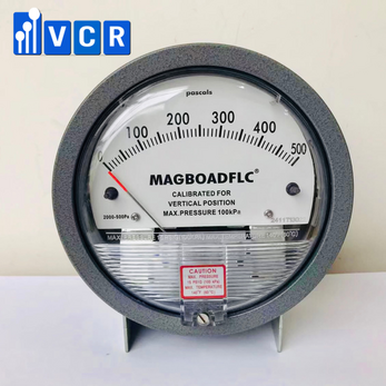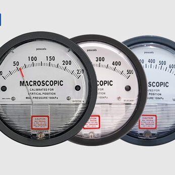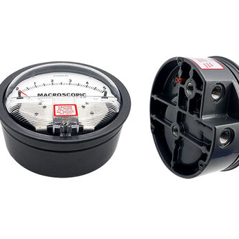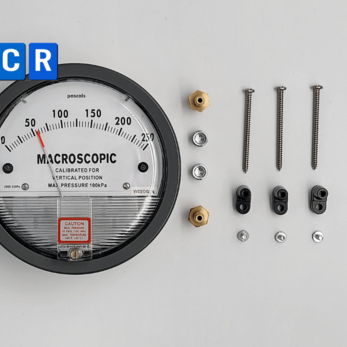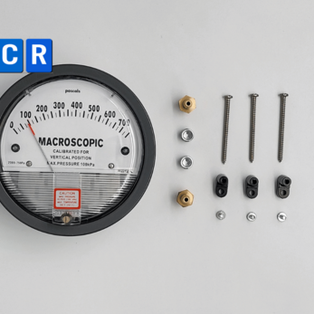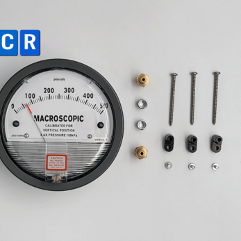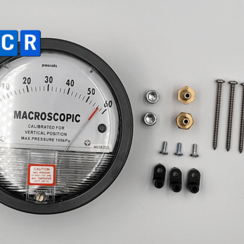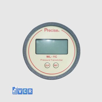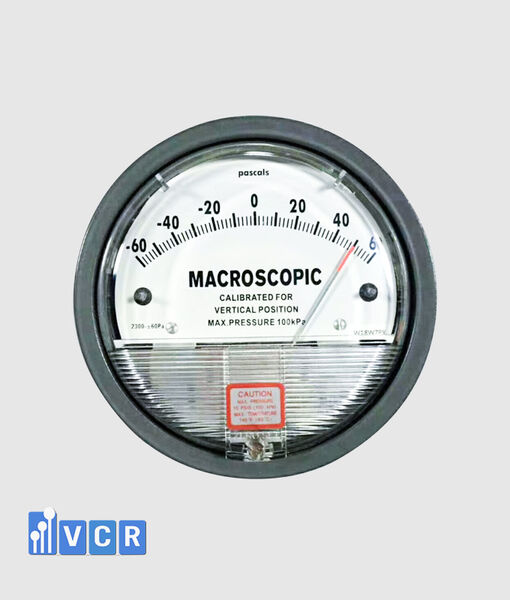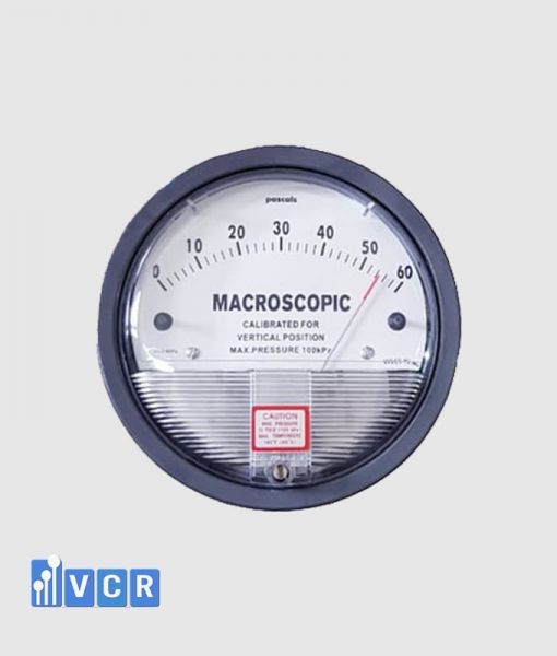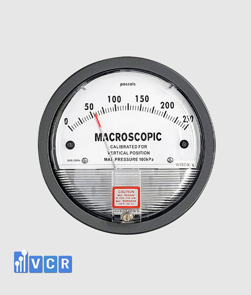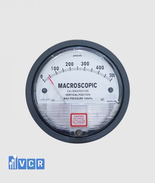

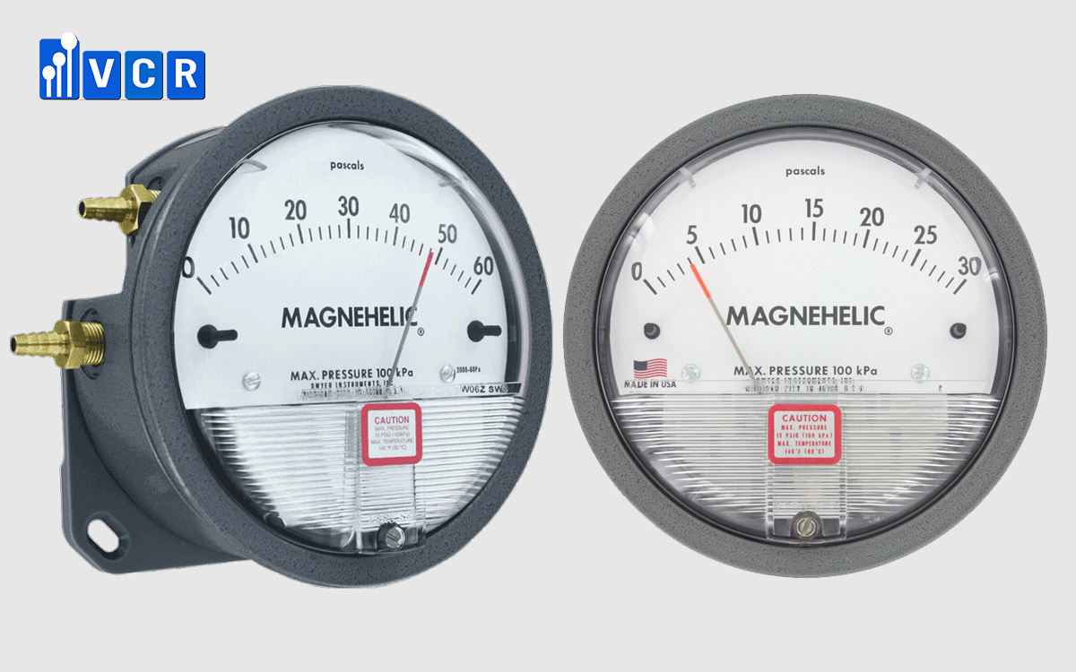
Under PIC/S GMP, a differential pressure gauge should be suitable for its intended use, have an appropriate range and accuracy, and be calibrated, periodically checked and included in qualification activities. Critical pressure differentials require monitoring, recording and alarms based on risk.
- What are the basic requirements?
- Which PIC/S documents apply?
- Intended use
- Measuring range
- Accuracy and resolution
- Pressure differences between cleanroom grades
- Continuous monitoring
- Can a mechanical gauge be used?
- Are 4–20 mA and Modbus mandatory?
- Alarm requirements
- Calibration
- Installation
- BMS and EMS integration
- Electronic data
- URS and DQ
- FAT and SAT
- Installation qualification
- Operational qualification
- PQ and requalification
- HEPA filter differential pressure
- Audit documentation
- Frequently asked questions
- Conclusion
What are the basic requirements?
PIC/S GMP does not prescribe one manufacturer, model, display technology or measuring range for every cleanroom.
The instrument must be suitable for its intended use, provide an appropriate range and precision, be correctly installed, calibrated and periodically checked, and be supported by documented evidence that the measurement remains under control.
For sterile manufacturing, pressure differentials identified as critical must be continuously monitored and recorded. The system should immediately warn operators of air-supply failure or pressure reduction below the approved limit. Other pressure differentials should still be monitored and recorded at defined intervals.
The suitability of a differential pressure gauge therefore cannot be determined only from the brand or factory certificate. The complete measurement chain should be assessed, including pressure taps, tubing, indication, signal transmission, alarms, data storage and calibration.
Which PIC/S documents apply?
The current PIC/S publication list identifies PE 009-17, dated 25 August 2023, as the PIC/S GMP Guide, including Part I, Part II and the Annexes.
The main sections relevant to differential pressure measurement are:
-
Part I, Chapter 3 for premises, measuring equipment and calibration.
-
Part I, Chapter 5 for cross-contamination control.
-
Annex 1 for sterile cleanroom pressure monitoring.
-
Annex 11 for BMS, EMS and other computerised systems.
-
Annex 15 for URS, DQ, FAT, SAT, IQ, OQ, PQ and requalification.
Not every Annex 1 provision should automatically be applied to every non-sterile facility. The scope should reflect the product, process, cleanroom classification and documented risk assessment.
Intended use
The user should first define what the instrument will measure.
Possible applications include room-to-room pressure, cleanroom-to-corridor pressure, cleanroom-to-airlock pressure, HEPA filter pressure drop, AHU filter resistance and equipment-plenum pressure.
Each application has a different operating range, resolution, monitoring frequency and criticality.
PIC/S Part I requires measuring equipment of an appropriate range and precision to be available for production and control operations.
Measuring range
PIC/S GMP does not require a universal 0–60 Pa, 0–125 Pa or 0–500 Pa scale.
Low ranges may be appropriate for room pressure, while wider ranges may be required for HEPA filters, bag filters and AHU filter banks.
The final range should be based on the approved operating value, alarm and action limits, filter initial resistance, final resistance, airflow and worst-case conditions.
An excessively wide range provides poor readability. A range that is too narrow can be exceeded during system fluctuation or filter loading.
Accuracy and resolution
PIC/S GMP does not define one accuracy class for every differential pressure gauge.
Accuracy should be suitable for the operating range and for the separation between normal, alert and action limits.
The specification should consider full-scale accuracy, reading accuracy, resolution, repeatability, hysteresis, zero drift, temperature influence and mounting orientation.
Part I requires measuring, recording and control equipment to be calibrated and checked at defined intervals by appropriate methods, with adequate records maintained.
Pressure differences between cleanroom grades
For sterile manufacturing, PIC/S Annex 1 gives a guidance value of at least 10 Pa between adjacent cleanrooms of different grades. This is a guidance value rather than a universal pressure requirement for every room or product.
Pressure arrangements may need to be modified for pathogenic, highly toxic, radioactive or biological materials where containment is necessary.
For non-sterile manufacturing, Part I requires risk-based prevention of cross-contamination arising from dust, gases, vapours, aerosols and other contaminants. The pressure strategy should therefore be based on the actual contamination and containment risk rather than copied directly from Annex 1.
Continuous monitoring
Annex 1 requires pressure-difference indicators between cleanrooms and between isolators and their backgrounds. Setpoints and criticality should be addressed within the Contamination Control Strategy.
Pressure differentials identified as critical should be continuously monitored and recorded. The warning system should indicate air-supply failure and pressure reduction below the approved limits.
Alarm delays should be assessed and justified within the CCS. Other pressure differentials should be monitored and recorded at regular intervals.
This does not mean that every filter gauge must be connected to an EMS. Measurement points should be classified according to their impact on product protection, containment and facility control.
Can a mechanical gauge be used?
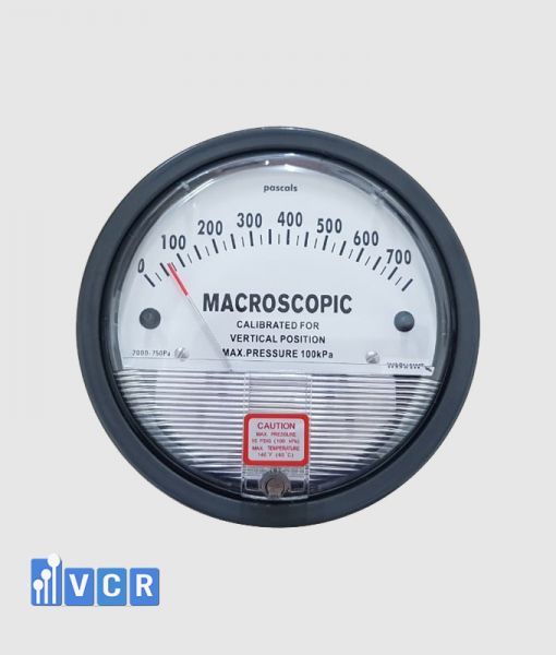
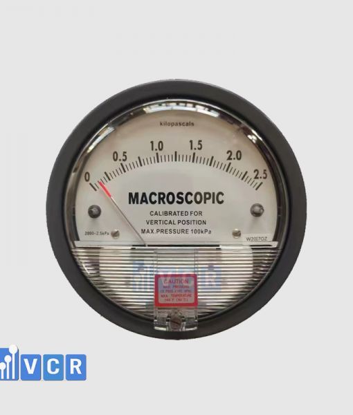
A mechanical pointer gauge can be suitable in a PIC/S GMP facility when it is appropriate for the measurement duty and managed under the quality system.
It should have a readable scale, suitable range, acceptable error, appropriate installation and a defined calibration programme.
Mechanical gauges are practical for local observations and manual records. However, a basic model cannot automatically record data or generate remote alarms.
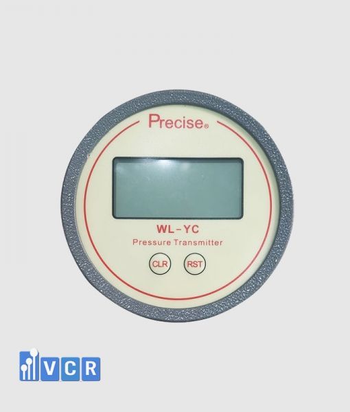
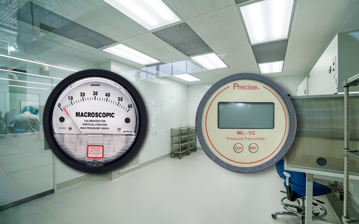
For critical points requiring continuous records, an electronic transmitter or a combined mechanical and electronic arrangement is normally needed to meet the monitoring objective of Annex 1.
Are 4–20 mA and Modbus mandatory?
PIC/S GMP does not mandate a specific signal type.
A 4–20 mA transmitter is commonly used for PLC, BMS and EMS integration. Modbus may be selected when several devices need to share a digital network or when additional diagnostic information is required.
The selected architecture should reliably detect low pressure, signal loss, power failure and communication failure.
The measurement should not interpret a broken wire or unpowered sensor as a valid zero-pressure condition.
Alarm requirements
The alarm strategy should define setpoints, delays, hysteresis, messages and the required operator response.
For critical pressure differentials, Annex 1 requires an immediate warning of air-supply failure or pressure reduction below the set limit. A warning should not be overridden without assessment, and a procedure should define the response to the alarm.
Alarm delays used to avoid short door-opening alarms should be risk-assessed and justified within the CCS.
OQ testing should include normal conditions, low-pressure alarms, high-pressure alarms where relevant, signal failure, broken wiring and sensor power loss.
Calibration
PIC/S Part I requires measuring, recording and control equipment to be calibrated and checked at defined intervals by appropriate methods. Adequate records must be maintained.
Calibration is more than returning the pointer to zero. The gauge should be compared with a suitable differential-pressure reference at several points.
For an electronic transmitter, calibration should verify the applied pressure, local indication, 4–20 mA or 0–10 V output, PLC/HMI value and alarms.
The calibration interval should be justified according to criticality, manufacturer recommendations, operating conditions and historical drift.
Installation
The High port should connect to the higher-pressure side and the Low port to the lower-pressure side.
Across a filter, High is upstream and Low is downstream.
Pressure taps should represent static pressure and should be located away from fans, dampers, supply diffusers and highly turbulent airflow.
Tubing should be airtight, clearly identified, free from kinks and protected against condensation.
The instrument should be mounted in the orientation specified by the manufacturer.
BMS and EMS integration
Not every differential pressure point must be connected to a central system.
Local gauges may be sufficient for low-risk maintenance measurements when an appropriate manual inspection programme is in place.
Critical measurements requiring continuous monitoring and recording should use an appropriate electronic system.
When a BMS or EMS is used for GMP activities, PIC/S Annex 11 requires the application to be validated, the IT infrastructure to be qualified and lifecycle controls to be based on a documented assessment of patient safety, data integrity and product quality.
Electronic data
Electronic differential-pressure records should be protected through access control, data storage, backup and change management.
Annex 11 requires risk-based consideration of audit trails for GMP-relevant changes and deletions. The reason for changing or deleting GMP-relevant data should be documented, and audit trails should be available, readable and periodically reviewed.
Computerised systems should be periodically evaluated to confirm that they remain validated and GMP compliant. Evaluation may include functionality, incidents, deviations, upgrades, security, reliability and validation status.
Critical systems also require a documented and tested business-continuity arrangement for system failure.
URS and DQ
Requirements should be defined in the URS before the instrument is selected.
The URS should specify the application, location, range, accuracy, units, display, output, alarm levels, delay, calibration, BMS/EMS interface and required documentation.
Annex 15 requires equipment, facility, utility and system requirements to be defined in a URS or functional specification, with quality requirements built into the design and GMP risks reduced to an acceptable level.
DQ should document that the proposed design complies with GMP and meets the URS.
FAT and SAT
FAT may verify the manufacturer, model, range, serial number, units, electrical supply, output signals and alarm functions before delivery.
Annex 15 allows equipment to be evaluated at the vendor site and requires confirmation against the URS or functional specification. FAT may be supplemented by SAT following installation at the manufacturing site.
An electronic pressure-monitoring FAT should challenge multiple pressure points, output scaling, alarms, delays, power failure, signal failure and data logging where applicable.
Installation qualification
IQ should confirm that the correct device has been installed at the approved location and according to the drawings and specifications.
Annex 15 identifies verification of instrumentation, pipework, services, supplier instructions, maintenance requirements, calibration and construction materials as IQ considerations.
For differential pressure points, IQ normally verifies the tag number, serial number, measuring range, units, High–Low connections, tubing, power, wiring, calibration certificate and technical documents.
Operational qualification
OQ demonstrates that the system performs as designed throughout its anticipated operating range.
Annex 15 requires tests based on process and system knowledge, including confirmation of upper and lower operating limits and worst-case conditions where appropriate.
Typical OQ tests include multi-point accuracy, zero return, increasing and decreasing pressure, alert and action alarms, delay, hysteresis, signal failure and HMI values.
Where the measurement controls a fan or damper, the complete control loop should be challenged.
PQ and requalification
PQ demonstrates effective and reproducible performance under routine process conditions.
Room-pressure PQ may consider door status, operator occupancy, equipment operation, material movement and at-rest and operational conditions.
Annex 15 requires equipment, facilities, utilities and systems to be evaluated at an appropriate frequency to confirm that they remain in a state of control. Requalification intervals and criteria should be justified.
HEPA filter differential pressure
A HEPA filter gauge should cover the range from clean-filter resistance to the expected final operating limit.
Readings should be compared under similar airflow conditions because filter pressure drop changes with airflow.
Differential pressure does not prove HEPA filter integrity. A damaged seal, torn media or bypass path may still produce a pressure reading. Integrity should be demonstrated through an appropriate leak test.
Filter alarm limits should be based on manufacturer data, airflow requirements, fan capability and qualified system limits rather than one universal replacement value.
Audit documentation
A PIC/S audit file should demonstrate the complete lifecycle of the measurement point.
Relevant records may include the URS, DQ, datasheet, drawings, instrument list, FAT/SAT, IQ/OQ/PQ, calibration certificates, operating procedures, alarm-response procedures, maintenance records and deviation history.
Electronic systems may additionally require range configuration, scaling records, alarm lists, user-access records, audit trails, backup arrangements, change control and periodic review.
The objective is to show that the measurement was correctly specified, qualified, operated and maintained in a state of control.
Frequently asked questions
Does PIC/S GMP specify an approved brand?
No. Suitability is determined by intended use, range, accuracy, calibration, qualification and lifecycle control.
Can a mechanical gauge comply with PIC/S GMP?
Yes, for suitable local-indication applications. Critical points requiring continuous records generally require an additional electronic transmitter or monitoring system.
Is 4–20 mA mandatory?
No. The signal may be 4–20 mA, 0–10 V or digital communication if the complete system meets the monitoring requirement and is qualified.
Is EMS integration mandatory?
Not for every point. Critical differentials that require continuous monitoring and recording need an appropriate qualified electronic solution, which may be an EMS, BMS or another validated platform.
How often should the gauge be calibrated?
PIC/S requires calibration at defined intervals but does not provide one interval for every instrument. The frequency should be justified through risk, history and operating conditions.
Is 10 Pa mandatory for every cleanroom?
No. Annex 1 provides 10 Pa as a guidance value between adjacent rooms of different grades in sterile manufacturing. The approved design should be based on the CCS and risk assessment.
Conclusion
A differential pressure gauge in a PIC/S GMP facility is part of a control system rather than merely a local display.
The instrument should have a suitable intended use, range, accuracy and resolution, correct High–Low connections, calibration, defined operating limits and documented responses to deviations.
For sterile manufacturing, critical pressure differentials require continuous monitoring and recording. Alarm delays must be assessed and justified within the CCS.
When measurements are managed through a BMS or EMS, the computerised system should meet Annex 11 validation and data-integrity expectations. The complete measurement chain should be addressed in URS, DQ, FAT/SAT, IQ, OQ, PQ and requalification under Annex 15.
VCR Cleanroom Equipment supplies mechanical differential pressure gauges, electronic indicators and transmitters with 4–20 mA, 0–10 V and Modbus outputs for cleanrooms, AHUs, HEPA boxes, pass boxes, air showers, FFUs, laminar airflow units and dispensing booths. VCR also supports range selection, alarm configuration, calibration, loop checks and FAT, IQ and OQ documentation for PIC/S GMP projects.