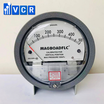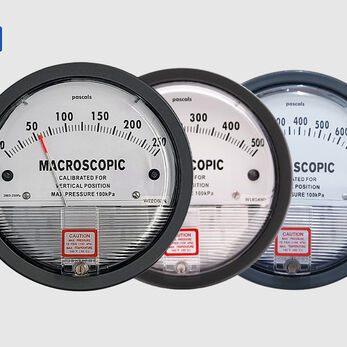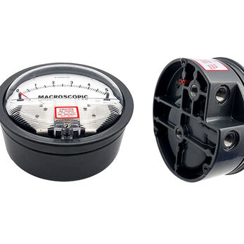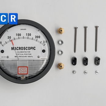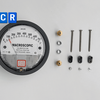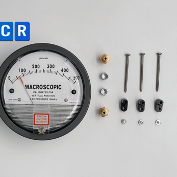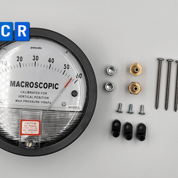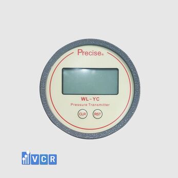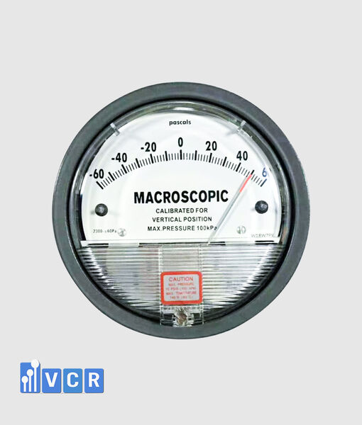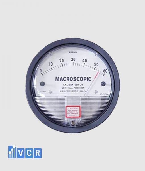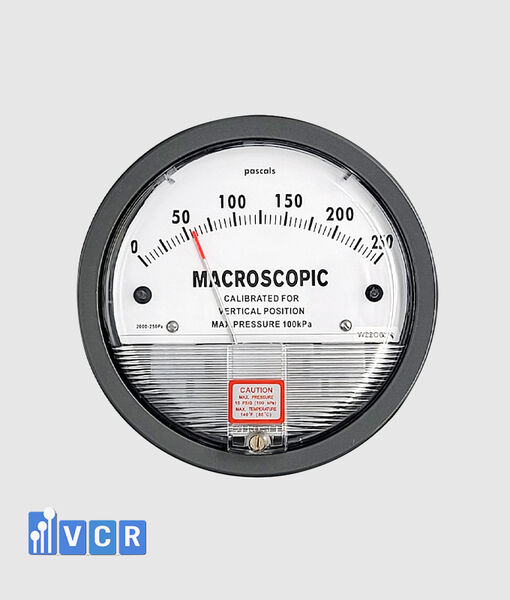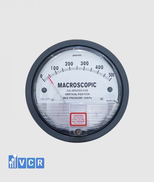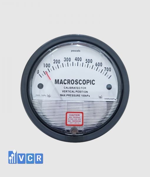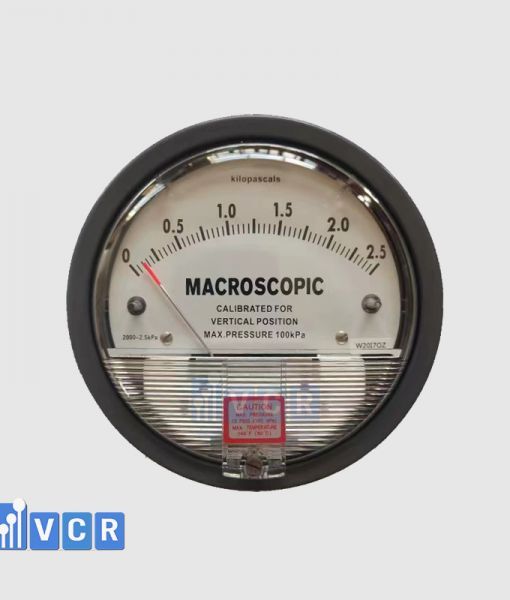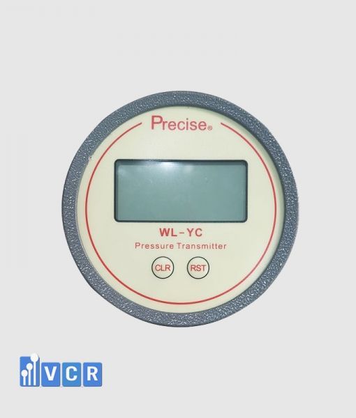

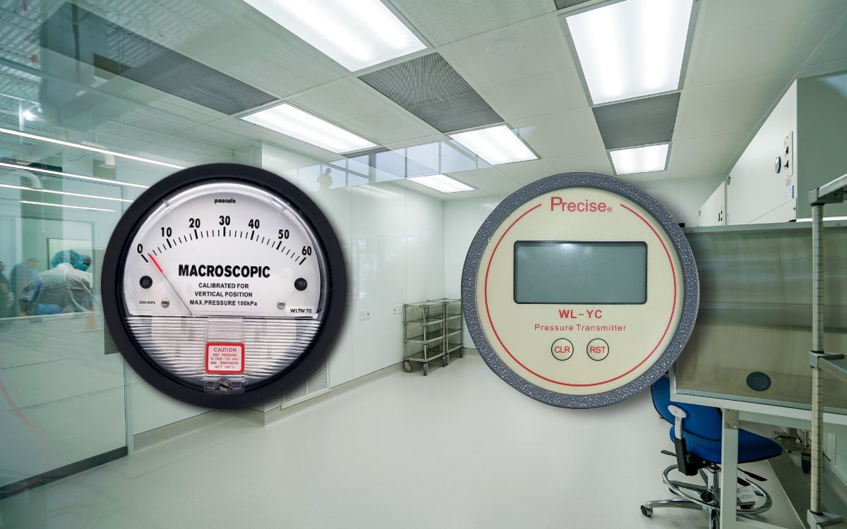
A differential pressure gauge measures the pressure difference between two points and is commonly installed in cleanrooms, AHUs, HEPA filters and HVAC equipment. Correct range selection, pressure tapping and High–Low connection are essential for reliable results.
- What is a differential pressure gauge?
- Operating principle
- Mechanical and electronic principles
- What is the measuring range?
- Why is range selection important?
- Selecting a range for cleanroom pressure
- Selecting a range for pre-filters and bag filters
- Selecting a range for HEPA filters
- Systems with variable fan speed
- Selecting the installation location
- Installing a gauge between two rooms
- Installing a gauge across a filter
- Pressure tubing requirements
- Mechanical gauge installation
- Electronic gauge installation
- Post-installation testing
- Common installation mistakes
- Calibration requirements
- Can one gauge be used for every application?
- Frequently asked questions
- Conclusion
What is a differential pressure gauge?
A differential pressure gauge measures the pressure difference between two locations in the same system.
Unlike a conventional pressure gauge, which measures pressure at one point, a differential pressure gauge receives pressure from two separate connections and determines the difference between them.
In cleanrooms, the instrument is commonly used to monitor the pressure difference between a production room and a corridor, between two rooms with different cleanliness levels or between a clean area and an adjacent support space.
In filtration systems, it measures pressure loss across a pre-filter, bag filter, HEPA filter or other air-treatment component.
Differential pressure gauges are widely used on AHUs, HEPA boxes, pass boxes, air showers, fan filter units, laminar airflow units, dispensing booths, sampling booths and other HVAC equipment.
Operating principle
A differential pressure gauge normally has two connections marked High and Low, or “+” and “−”.
The High port is connected to the higher-pressure location. The Low port is connected to the lower-pressure location.
The measurement is calculated as:
Differential pressure = High-port pressure − Low-port pressure
For example, when a positive-pressure cleanroom is compared with a corridor, the High port is usually connected to the cleanroom and the Low port to the corridor.
When measuring a HEPA filter, the High port is connected upstream and the Low port downstream. As particles accumulate on the filter media, resistance normally increases and the pressure difference rises when airflow remains comparable.
Differential pressure should not be interpreted without considering operating conditions. Changes in fan speed, damper position and airflow can affect the reading even if the filter condition has not significantly changed.
Mechanical and electronic principles
A mechanical differential pressure gauge normally uses a diaphragm, capsule or magnetic mechanism.
When a pressure difference occurs, the sensing element moves or deflects. This movement is transferred to a pointer on the graduated dial.
Most mechanical gauges require no external power and are suitable where only local indication is required.
An electronic differential pressure gauge uses a pressure sensor to convert the pressure difference into an electrical signal.
The internal circuit amplifies, compensates and converts the signal into a digital value. Depending on the model, the device may provide relay alarms, 4–20 mA, 0–10 V, RS485 or Modbus communication.
An electronic instrument with a local display and signal output may function as both a gauge and a differential pressure transmitter.
What is the measuring range?
The measuring range is the minimum-to-maximum differential pressure that the instrument can display or measure.
For example, a 0–60 Pa gauge displays differential pressure from zero to 60 pascals.
Bidirectional ranges such as −30 to +30 Pa or −60 to +60 Pa are also available. These ranges are useful where a room may operate under either positive or negative pressure.
Common ranges used in cleanrooms and HVAC systems include 0–30 Pa, 0–60 Pa, 0–125 Pa, 0–250 Pa, 0–500 Pa, 0–750 Pa, 0–1,000 Pa and 0–2,500 Pa.
Common units include Pa, kPa, mmH₂O, mbar and in.w.c.
Why is range selection important?
Correct range selection directly affects readability, resolution and instrument protection.
If the range is too wide, small pressure changes become difficult to observe. A 0–1,000 Pa gauge is not suitable for clearly monitoring a room-pressure difference of only a few tens of pascals.
If the range is too narrow, the pointer or sensor may exceed full scale during system fluctuation, increased fan speed or filter loading.
The range should exceed the maximum expected operating value but should not be unnecessarily large. A reasonable allowance should be included for normal variation and abnormal conditions.
Range selection should not be based only on the equipment category. Two AHUs of similar size may require different ranges because of differences in airflow, filter type and fan arrangement.
Selecting a range for cleanroom pressure
Cleanroom pressure differences are generally low, so the gauge should provide a low range and sufficient resolution.
Ranges such as 0–60 Pa or 0–125 Pa are commonly considered, but they are not universal requirements.
The selected range should reflect the design differential pressure, warning level, action limit and normal system fluctuation.
Negative-pressure rooms often benefit from a negative or bidirectional scale. A positive-only gauge may be difficult to interpret if the connections are reversed to represent negative pressure.
Isolation rooms, microbiology rooms, dispensing areas and pharmaceutical cleanrooms may require an electronic gauge with alarm capability.
Selecting a range for pre-filters and bag filters
Pre-filters and bag filters in AHUs generally produce a higher pressure drop than room-pressure applications.
The gauge range must cover both initial resistance and the expected final resistance of the filter.
The filter datasheet should be reviewed to identify the initial pressure drop at design airflow and the recommended final resistance.
Depending on the filter and airflow, ranges such as 0–500 Pa, 0–750 Pa or 0–1,000 Pa may be more suitable than a low room-pressure range.
Using one range for every filter stage is a common mistake. Each filter stage should be reviewed separately.
Selecting a range for HEPA filters
HEPA filters have pressure-drop characteristics that differ from pre-filters and bag filters.
The selected range must be based on manufacturer data and actual airflow.
HEPA boxes, FFUs, pass boxes and air showers often require ranges in the hundreds of pascals, but no single value is suitable for all equipment.
A large filter operating at a low face velocity may have a much lower pressure drop than a smaller filter operating at a higher face velocity.
For filter-clogging monitoring, the gauge should display the full progression from clean-filter resistance to the replacement or action limit.
Systems with variable fan speed
In systems using variable-frequency drives, airflow and filter pressure drop change with fan speed.
If the fan increases speed to compensate for filter loading, differential pressure may rise more rapidly.
Range selection should therefore consider the maximum fan speed as well as normal operation.
When differential pressure is used as a control signal, an electronic sensor with 4–20 mA or Modbus output is generally more suitable than a basic mechanical gauge.
Control logic should include limits, delay and anti-oscillation functions.
Selecting the installation location
The gauge should be easy to observe but should not interfere with cleaning, maintenance or equipment access.
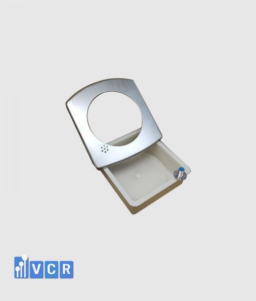
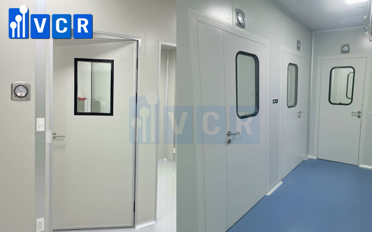
A cleanroom pressure gauge is commonly flush-mounted near the room entrance. This allows operators to inspect pressure before entering without accessing an HMI.
A filter gauge is normally installed on the AHU casing, equipment panel or technical enclosure. Pressure tubing is routed from the upstream and downstream sides of the filter.
The gauge should be protected from excessive vibration, impact, unsuitable temperature and inaccessible mounting positions.
Electronic instruments also require consideration of power supply, signal wiring and control-panel location.
Installing a gauge between two rooms
The first step is to identify which room is designed to operate at the higher pressure.
The High port is connected to the higher-pressure room and the Low port to the lower-pressure room.
The pressure tapping point should be located away from supply diffusers, return grilles, door gaps and areas of strong turbulence.
A tapping point installed too close to a door may produce large fluctuations when the door opens or closes.
Any tubing penetration through a cleanroom panel should be sealed. An unsealed penetration can create an air leak and affect the pressure difference being measured.
The final reading should be checked with doors closed and the HVAC system operating under stable conditions.
Installing a gauge across a filter
For filter monitoring, the High port must be connected upstream and the Low port downstream.
Both tapping points should represent static pressure. They should not face a high-velocity air stream directly because dynamic pressure may distort the result.
Pressure tubes should be clearly identified as High and Low. Reversed connections may cause a negative, reverse or unreasonable reading.
A separate pair of tapping points should be used for each filter stage when the operator must identify which filter is loaded.
A gauge measuring the total resistance of several filters cannot identify the individual filter responsible for the pressure increase.
Pressure tubing requirements
Pressure tubing has a major influence on measurement reliability.
Tubing must be airtight, free from kinks and protected against compression. Connections should be secure without deforming the tube.
Excessively long tubing, multiple bends or water accumulation may slow the response and produce unstable readings, particularly at low differential pressure.
Tubing should be fixed to prevent vibration and should be protected from heat and mechanical damage.
Where condensation is possible, the tubing arrangement should prevent water accumulation. Liquid inside the tubing creates an additional hydrostatic pressure and causes measurement error.
Mechanical gauge installation
A mechanical gauge should be installed in the orientation specified by the manufacturer.
Some instruments are calibrated for vertical mounting and may show an offset if installed at an angle.
Before connecting pressure tubing, the pointer should be checked at equal pressure. It should indicate zero.
A small offset may be corrected using the zero-adjustment screw where permitted. Zero adjustment does not replace calibration.
The dial should be installed at a convenient height and viewing angle to reduce parallax error.
The instrument should be protected from impact and long-term mechanical vibration.
Electronic gauge installation
An electronic gauge requires pressure tubing, power wiring and signal wiring.
Before energising the device, the installer should verify supply voltage, polarity, output type and compatibility with the PLC or BMS.
For 4–20 mA devices, the wiring type must be confirmed as two-wire, three-wire or four-wire.
For RS485 or Modbus, the device address, baud rate, parity and network termination may need to be configured.
Signal cables should be separated from motor and variable-frequency-drive cables to reduce electrical interference.
After installation, both the local display and the HMI value should be checked. A difference may indicate incorrect range configuration or scaling.
Post-installation testing
Commissioning should include more than checking whether the display is active.
The zero position should first be verified with both pressure ports at equal pressure. High and Low connections should then be confirmed.
The system should be operated under stable conditions and the initial value recorded. For a new filter, this becomes a useful baseline for future trend monitoring.
If alarms are included, the system should be tested below, at and above each setpoint.
For 4–20 mA devices, a loop check should verify that 4 mA, 12 mA and 20 mA correspond to the low, mid and high points of the configured range.
Common installation mistakes
Reversing the High and Low ports is one of the most common errors.
Leaking tubing causes the displayed value to be lower than the actual pressure difference. Blocked tubing may produce a slow or unchanging response.
A pressure tapping point installed near a fan, damper or diffuser may cause excessive fluctuation. This is often a tapping-location problem rather than a gauge defect.
An unnecessarily wide range may make important changes almost invisible.
For electronic instruments, incorrect PLC scaling is a frequent reason for differences between the local display and the HMI value.
Calibration requirements
Differential pressure gauges should be inspected and calibrated according to measurement criticality, quality-system requirements and facility procedures.
Measurements used for GMP cleanrooms, HEPA filter alarms, fan control or acceptance testing normally require documented calibration.
Calibration involves more than checking zero. The instrument should be compared with a reference pressure source at several points across the range.
For electronic instruments, the output signal, relay function and HMI value should also be tested.
The calibration interval should be based on risk assessment, usage, historical drift and manufacturer recommendations.
Can one gauge be used for every application?
Many gauges can technically measure both room pressure and filter pressure drop, but one model should not automatically be used for every application.
A 0–60 Pa gauge may suit room-pressure monitoring but may be unsuitable for a loaded filter. A 0–1,000 Pa gauge may suit an AHU filter but provide poor resolution for room pressure.
Applications requiring alarms or data logging should use electronic instruments. Simple local points may use mechanical gauges.
The correct device is not necessarily the one with the most features. It is the one with the correct range, accuracy and output for the intended task.
Frequently asked questions
Is a differential pressure gauge the same as a pressure-difference gauge?
Yes. Both terms describe an instrument that measures the difference between two pressure points.
How should the High and Low ports be connected?
The High port connects to the higher-pressure point and the Low port to the lower-pressure point. Across a filter, High is upstream and Low is downstream.
Can a 0–60 Pa gauge be used for a HEPA filter?
Only when the actual filter pressure drop remains within that range. The initial and final filter resistance should be checked before selection.
Why does the gauge display a negative value?
The High and Low ports may be reversed. A negative value may also be normal when a bidirectional gauge is used for a negative-pressure room.
Why does the pointer not return to zero?
Possible causes include incorrect mounting orientation, trapped pressure, zero drift or calibration error.
Is an electronic gauge always more accurate?
No. Electronic instruments often provide higher display resolution, but actual accuracy depends on the model, range and calibration condition.
Conclusion
A differential pressure gauge compares pressure at the High and Low ports. It can be used for room-pressure monitoring, filter pressure-drop measurement and HVAC system evaluation.
The three most important factors are selecting the correct range, locating representative pressure tapping points and connecting the High and Low ports correctly.
The measuring range should cover the maximum expected value without being unnecessarily wide. Pressure tapping points should represent static pressure and avoid turbulent airflow. Tubing must be airtight, free from kinks and protected from condensation.
Mechanical gauges are practical for simple local indication. Electronic gauges and transmitters are preferable when alarms, data transmission or control functions are required.
VCR Cleanroom Equipment supplies mechanical differential pressure gauges, electronic gauges and sensors with 4–20 mA, 0–10 V and Modbus outputs for cleanrooms, AHUs, HEPA boxes, pass boxes, air showers, FFUs, laminar airflow units and dispensing booths. VCR also supports range selection, accessories, installation, calibration and commissioning.