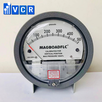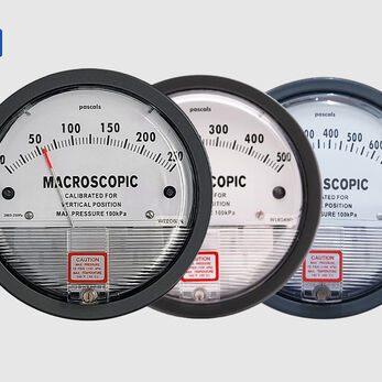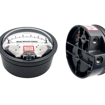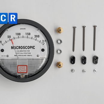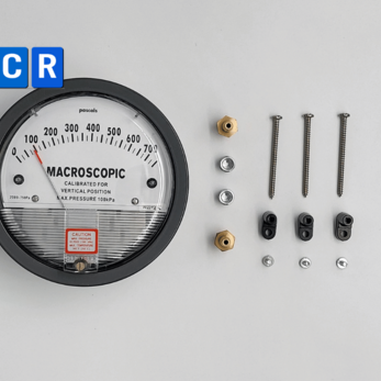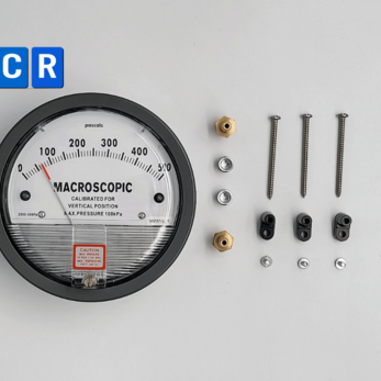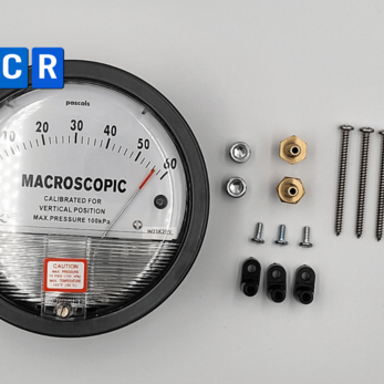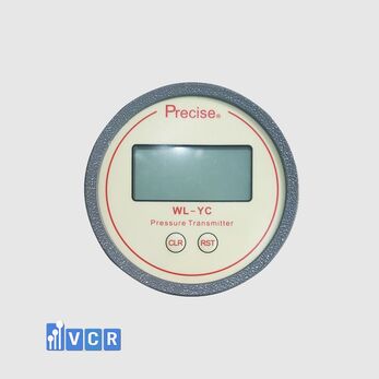

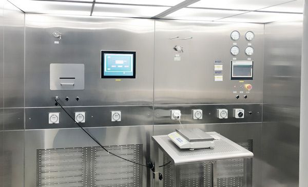
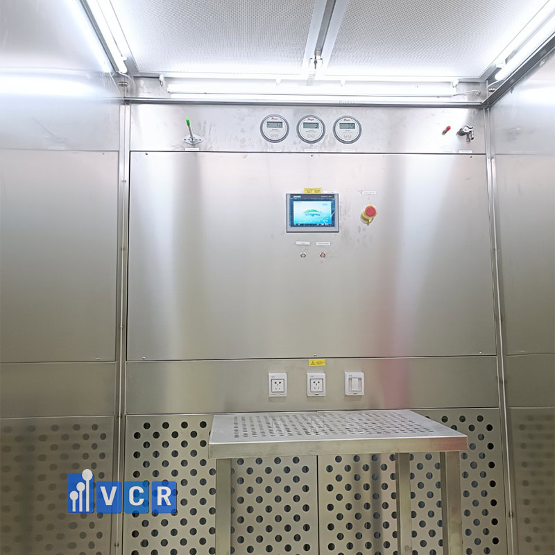
A weighing-booth differential pressure gauge monitors room pressure, filter loading and airflow-control conditions. Under GMP, it should have an appropriate range, correct High–Low connections, defined limits, calibration and risk-based alarm testing.
- What is the purpose of a differential pressure gauge in a weighing booth?
- Does GMP require a differential pressure gauge?
- Sterile and non-sterile GMP should not be confused
- What pressure points should be monitored?
- How many gauges are required?
- How should the measuring range be selected?
- What accuracy is required?
- Mechanical or electronic gauge?
- Is PLC or HMI integration required?
- Normal, alert and action limits
- Installation requirements
- FAT requirements
- IQ and OQ requirements
- Calibration and records
- Common mistakes
- Frequently asked questions
- Conclusion
What is the purpose of a differential pressure gauge in a weighing booth?
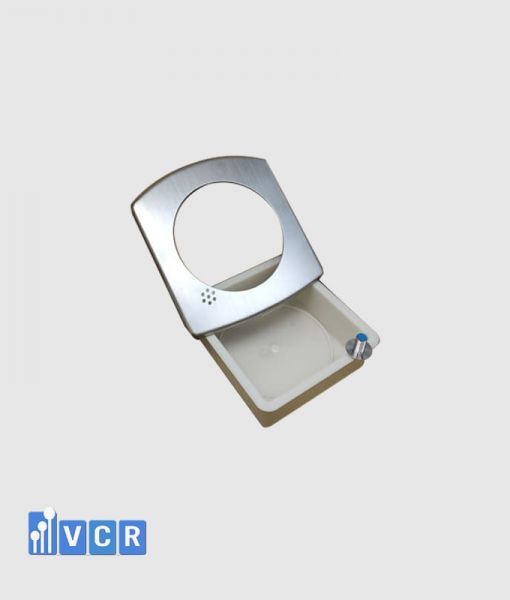
A weighing booth, also known as a dispensing booth or reverse-laminar-airflow booth, provides a controlled environment for weighing, dispensing or sampling materials that may generate dust.
For many non-sterile pharmaceutical applications, the booth uses downward airflow and low-level return air to contain dust, protect the operator and reduce cross-contamination risk.
WHO guidance states that weighing and dispensing areas should have suitable environmental classification, material and personnel flow, pressure differentials, dust control and air-change rates. The purpose of the booth is to provide containment and operator protection, while vertical airflow also helps protect the material from contamination generated by the operator.
A differential pressure gauge does not create GMP compliance by itself. It provides operating evidence that filters, fans and the approved pressure strategy remain under control.
Does GMP require a differential pressure gauge?
GMP does not specify one universal gauge brand, model or measuring range for every weighing booth.
However, conditions affecting contamination control, airflow direction and pressure segregation must be identified, monitored and verified according to risk.
For non-sterile manufacturing, WHO requires room-pressure-difference indication. This may be provided by pressure gauges or suitable electronic systems such as an EMS or BMS.
The indication device should have a range and graduation that allow the value to be read with appropriate accuracy. Normal operating ranges, alert limits and action limits should be defined and displayed at the point of indication or on the EMS/BMS.
Pressure monitoring and control devices should be calibrated, compliance with specifications should be periodically verified and the results should be recorded. Alarm levels and justified delay times should be established through risk analysis.
The practical requirement is therefore to install a suitable pressure-indicating or transmitting device at every point where differential pressure is an identified control parameter.
Sterile and non-sterile GMP should not be confused
Most weighing booths used for powders, excipients and oral-solid-dose materials are non-sterile applications. WHO HVAC guidance for non-sterile products is therefore often the more directly relevant reference.
EU GMP Annex 1 primarily addresses sterile medicinal products. It requires pressure differences identified as critical to be continuously monitored and recorded, with an immediate warning when the air supply fails or pressure falls below the approved limit. Alarm delays should be assessed and justified within the contamination control strategy.
Annex 1 provides a guidance value of at least 10 Pa between adjacent cleanrooms of different grades in sterile manufacturing. This should not be treated as a universal requirement for every dispensing or weighing booth.
For dust-generating non-sterile operations, WHO requires each pressure differential to be individually assessed according to the material, process and level of protection required for the product, operator and environment.
What pressure points should be monitored?
A weighing booth may contain several independent differential-pressure measurements.
Room differential pressure indicates the relationship between the dispensing room, corridor, airlock or staging room. Where dust containment is required, the weighing area is commonly maintained below the pressure of adjacent clean areas, subject to the approved risk assessment and facility design.
Filter differential pressure indicates loading across pre-filters, medium filters or HEPA filters. Separate monitoring allows maintenance personnel to identify which filter stage is increasing in resistance.
HEPA differential pressure provides an operating indication of filter resistance. It does not prove filter integrity or particle-removal efficiency. HEPA leak testing remains a separate qualification activity.
Some designs also monitor plenum pressure or use a differential pressure sensor as feedback for fan-speed control. This measurement should not be confused with room pressure or filter pressure drop.
How many gauges are required?
There is no fixed GMP number.
A basic booth may have only one gauge across the HEPA filter, but this does not provide information about room pressure, pre-filter loading or the complete control system.
A more informative design may monitor each important filter stage and provide a separate room-pressure measurement where room segregation is part of the contamination-control or dust-containment strategy.
The required measuring points should be defined in the URS, risk assessment, P&ID and control philosophy. Each point should have a unique identification number, purpose, range, alarm limits and calibration requirement.
How should the measuring range be selected?
The selected range should exceed the maximum expected operating value without being unnecessarily wide.
An excessively wide range reduces readability and resolution. An excessively narrow range may be exceeded when filter resistance rises or the fan operates at maximum speed.
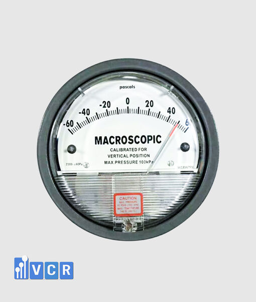
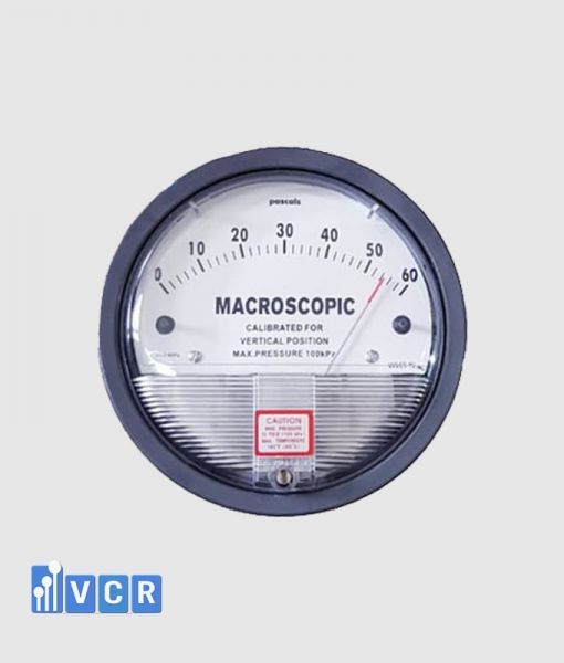
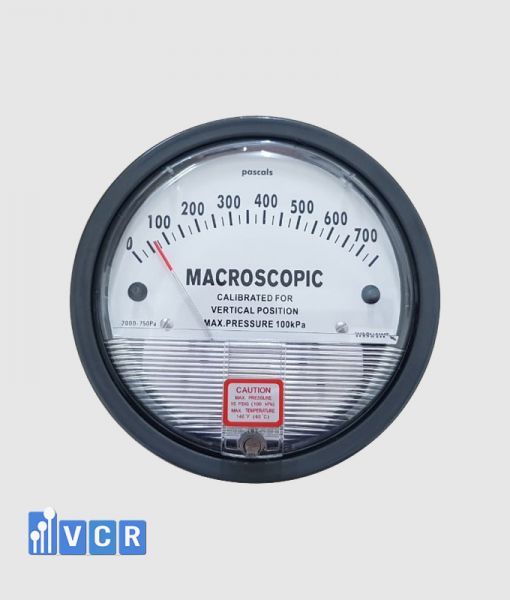
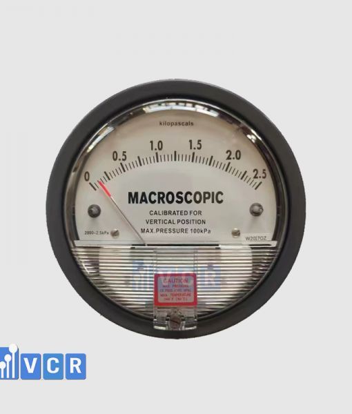
Low ranges such as 0–60 Pa, 0–125 Pa or a bidirectional scale may be considered for room-pressure monitoring. These are engineering examples rather than universal GMP requirements.
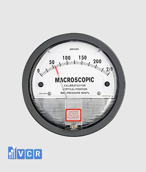
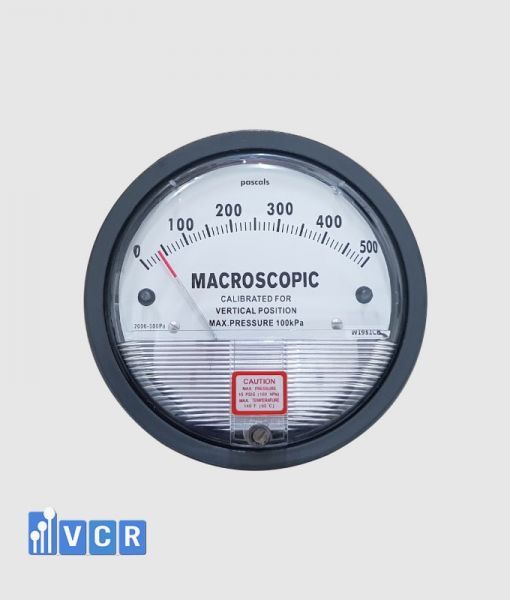
Filter monitoring may require ranges such as 0–250 Pa, 0–500 Pa, 0–750 Pa or 0–1,000 Pa, depending on the filter datasheet, design airflow, clean-filter resistance and final operating limit.
WHO does not prescribe one scale. It requires the gauge range and graduation to permit reading at an appropriate accuracy.
What accuracy is required?
GMP does not establish one common accuracy class for every weighing-booth pressure gauge.
Accuracy should be appropriate for the operating range, alarm limits and criticality of the measurement.
A device whose uncertainty is large compared with the difference between the normal range and alarm limit may not be suitable.
The specification should distinguish accuracy as a percentage of full scale from accuracy as a percentage of reading. Repeatability, hysteresis, zero drift, temperature effect, mounting orientation and overpressure capability should also be reviewed.
Calibration acceptance criteria should be derived from the URS, risk assessment and approved operating limits rather than applying one tolerance to all pressure points.
Mechanical or electronic gauge?
A mechanical gauge is suitable for direct local indication. It normally requires no external power and has a relatively simple installation.
Its limitations are the absence of automatic data logging, remote alarms and control-system output unless additional contacts or a transmitter are provided.
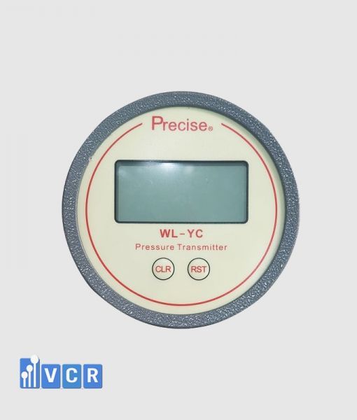
An electronic differential pressure gauge or transmitter is more suitable when the booth requires alarms, historical data or automatic control.
Typical outputs include 4–20 mA, 0–10 V, RS485 and Modbus.
At critical points, a mechanical gauge may be combined with an electronic transmitter. The mechanical instrument provides local indication, while the transmitter sends data to the PLC, HMI, BMS or EMS.
Is PLC or HMI integration required?
Integration should be considered when differential pressure affects dust containment, airflow, operator protection or product quality.
The control system can generate dirty-filter alarms, low-pressure alarms, event history and shutdown logic.
Where the signal is used for fan control, a PLC may apply PID or equivalent control to maintain an approved airflow or pressure condition.
Automatic fan control should include speed limits, delay, deadband, sensor-fault detection and a defined safe response during signal failure.
For critical pressure differences in sterile manufacturing, EU GMP Annex 1 requires continuous monitoring, recording and warning below the approved limit.
Normal, alert and action limits
Setpoints should not be selected only from supplier experience.
Room-pressure limits should be derived from the approved pressure cascade, door operation, dust-extraction system and normal operating variation.
Filter limits should be based on the clean-filter pressure drop at approved airflow, the manufacturer’s final resistance recommendation and the actual ability of the system to maintain airflow.
An alert limit should provide sufficient time for investigation and maintenance planning. The action limit should initiate an approved SOP response.
Alarm delays should reject short start-up or door-opening disturbances without masking a genuine deviation. WHO requires alarm delays to be risk-based and justified.
Installation requirements
The High port should be connected to the higher-pressure side and the Low port to the lower-pressure side.
Across a filter, High is upstream and Low is downstream. For room monitoring, the connection depends on the approved pressure cascade.
Pressure taps should represent static pressure and should not directly face high-velocity airflow near fans, dampers or supply diffusers.
Tubing should be airtight, free from kinks, protected from condensation and clearly identified.
Mechanical gauges should be installed in the manufacturer’s specified orientation. Their zero position should be checked when both ports are at equal pressure.
Where zero adjustment is available, it should be controlled to prevent unauthorised adjustment. WHO states that gauge zero setting should be tamper-proof and periodically checked.
FAT requirements
Factory acceptance testing should confirm the approved manufacturer, model, range, unit, device tag and installation location.
High and Low tubing should be verified against the drawing. The gauge should be tested at several differential-pressure values using a suitable reference source.
Where alarms or electrical outputs are included, the FAT should simulate normal, alert and action conditions.
For 4–20 mA outputs, the scaling between the transmitter, PLC and HMI should be verified.
The test should also evaluate signal loss, broken wiring, sensor power failure and out-of-range conditions.
IQ and OQ requirements
Installation qualification confirms that the correct device has been installed in the correct position, orientation and configuration.
IQ documentation may include the datasheet, calibration certificate, serial number, pressure-tubing diagram, wiring diagram, device tag and installation materials.
Operational qualification confirms that the measurement operates within the approved range.
OQ may include multi-point accuracy, zero return, alarm limits, delay, hysteresis, HMI indication and sensor-failure response.
For a weighing booth, pressure testing should be evaluated together with airflow velocity, airflow visualisation, filter integrity and dust-containment performance.
WHO guidance treats pressure differentials, dust control, airflow direction, air-change rates and the effect of airflow on balance sensitivity as related design considerations.
Calibration and records
Critical gauges and transmitters should be calibrated according to an approved schedule.
Calibration should use a suitable traceable reference and verify several points across the range.
For electronic transmitters, pressure input, electrical output and the value received by the PLC or HMI should be checked.
The calibration interval should reflect manufacturer recommendations, measurement criticality, operating environment and historical drift.
WHO requires pressure control and monitoring devices to be calibrated, periodically verified against specifications and supported by recorded results.
Common mistakes
A common mistake is installing one gauge across the complete filter bank and expecting it to identify the individual loaded filter.
Another is using a room-pressure range for a HEPA filter or using an excessively wide filter range for a low room-pressure measurement.
Some projects provide a gauge without defining normal, alert and action zones. The operator can see a value but has no approved response criterion.
Electronic devices are sometimes checked only at the local display, without verifying PLC scaling, HMI values and alarm records.
The 10–15 Pa values used in some cleanroom guidance should not be copied as a universal weighing-booth requirement. The pressure strategy must reflect the material, dust-containment objective and risk assessment.
Frequently asked questions
How many gauges does a weighing booth require?
GMP does not define one number. The requirement depends on room pressure, filter stages, control functions and risk.
Can a 0–60 Pa gauge be used?
It may be suitable for room pressure when the operating range is appropriate. It is often too low for filter-pressure-drop monitoring.
Can a HEPA pressure gauge detect a filter leak?
No. It indicates resistance only. Filter integrity requires an appropriate HEPA leak test.
Is an alarm required?
An alarm is required where pressure deviation could affect containment, the product, operator or environment. The setpoint and delay should be risk-based.
Is a mechanical gauge GMP-compliant?
It can be suitable when the range, readability, calibration and recording procedure meet the approved requirements. Critical points may require an additional electronic transmitter.
Does zero adjustment replace calibration?
No. Zero adjustment aligns the instrument at zero differential pressure. Calibration verifies accuracy at several pressure values.
Conclusion
A weighing-booth differential pressure gauge is part of the monitoring system for room pressure, filter loading and approved airflow-control conditions.
GMP does not prescribe one universal brand, range or number of gauges. The design should reflect the material, dust hazard, operator-protection requirement, cross-contamination risk and HVAC configuration.
The instrument should have an appropriate range and resolution, correct High–Low connections, defined normal, alert and action limits, calibration and documented FAT, IQ and OQ testing.
Electronic transmitters with 4–20 mA or Modbus outputs are useful where alarms, historical records or automatic control are required. Mechanical gauges remain valuable for direct local indication.
VCR Cleanroom Equipment supplies mechanical gauges, electronic indicators and differential pressure transmitters for dispensing booths, weighing booths and reverse-laminar-airflow systems. VCR also supports range selection, pressure tapping, alarm configuration, calibration, FAT, IQ, OQ and project commissioning.