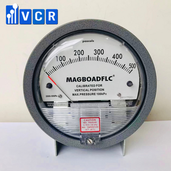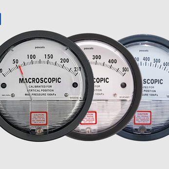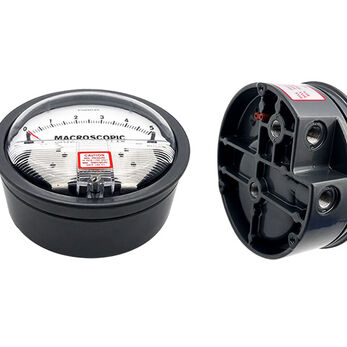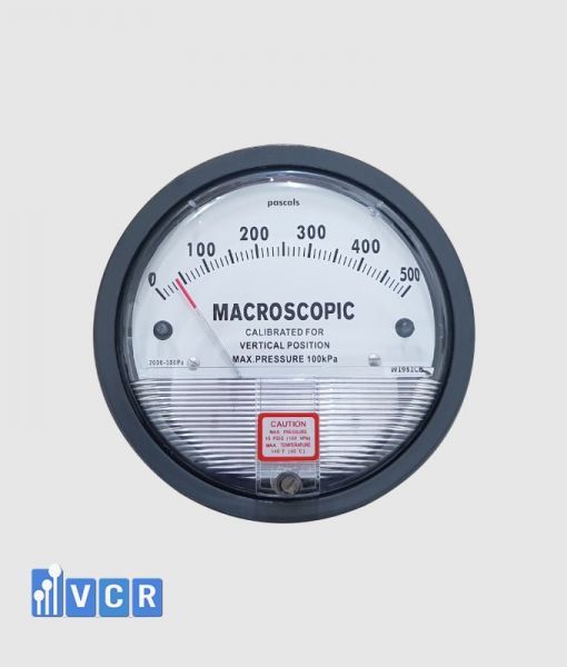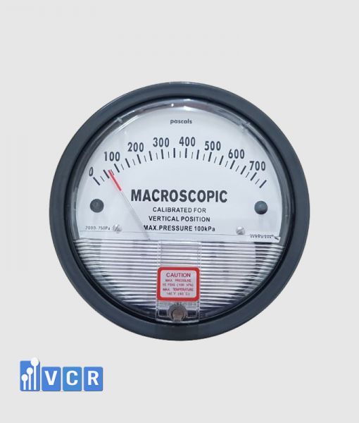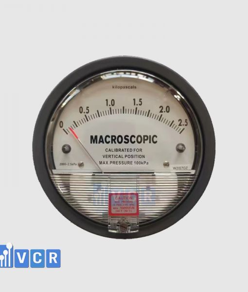

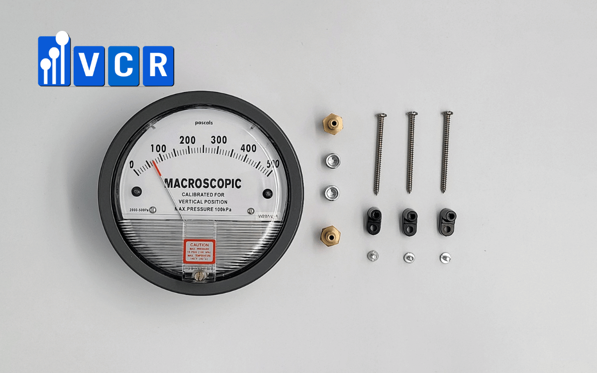
The Macroscopic 0–500 Pa differential pressure gauge is a mechanical pointer instrument used to monitor HEPA filters, fine filters and AHU filter stages. It requires no electrical supply and is suitable for HEPA boxes, FFUs, laminar airflow units, pass boxes and other cleanroom HVAC equipment.
- What is the Macroscopic 0–500 Pa gauge?
- Published technical specifications
- Operating principle
- Suitable applications
- Filter-loading monitoring
- HEPA filter application
- AHU application
- HEPA box application
- FFU application
- Laminar airflow and dispensing-booth applications
- Dynamic pass box and air-shower applications
- Can it be used for room pressure?
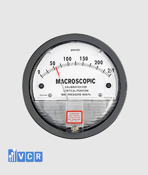
- Comparison with 0–250 Pa
- Comparison with 0–750 Pa
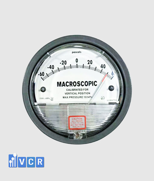
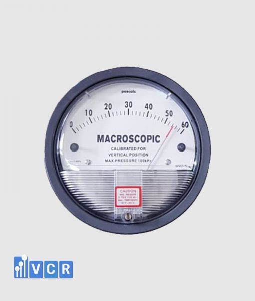
- Comparison with 0–60 Pa
- Supplied accessories
- Installation
- Zero checking
- Calibration
- GMP suitability
- Advantages
- Limitations
- When should this model be selected?
- Purchasing checks
- Frequently asked questions
- Conclusion
What is the Macroscopic 0–500 Pa gauge?
The Macroscopic 0–500 Pa differential pressure gauge is a mechanical pointer instrument that measures the pressure difference between two locations.
Its High port receives pressure from the higher-pressure side, while its Low port receives pressure from the lower-pressure side. The resulting difference is displayed directly in pascals.
The 0–500 Pa range is primarily suitable for filter-pressure-drop monitoring and applications with greater resistance than normal room-pressure measurements.
VCR’s published product information identifies the instrument as a Macroscopic Series 2000 model with a 0–500 Pa range and published accuracy of ±2% of full scale at 21°C. The product is intended for positive differential pressure, filters and higher-pressure-difference applications.
The mechanical indication requires no external electrical supply. It can be installed on AHUs, HEPA boxes, FFUs, laminar airflow units, dynamic pass boxes and other clean-air equipment.
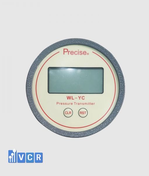
Where remote alarms, historical records or PLC integration are required, an electronic transmitter should be added or used instead.
Published technical specifications
| Parameter | Published value |
|---|---|
| Brand | Macroscopic |
| Product series | Series 2000 |
| Measuring range | 0–500 Pa |
| Display | Mechanical pointer |
| Published accuracy | ±2% of full scale at 21°C |
| Pressure limit | −20 inHg to 15 PSI |
| Operating temperature | Approximately −6.7 to 60°C |
| Medium | Air or compatible non-corrosive gases |
| Connections | 1/8-inch NPT |
| Power supply | Not required |
The Vietnamese product page lists a weight of approximately 560 g, while the English page lists approximately 510 g. Where the weight affects design documentation, the project should confirm the actual value from the supplied product datasheet.
An accuracy of ±2% of full scale corresponds to a nominal value of approximately ±10 Pa for the 0–500 Pa range.
This should be assessed against the actual operating region and project acceptance criteria.
Operating principle
The gauge operates by applying two pressure values to an internal sensing element.
When the High-port pressure exceeds the Low-port pressure, the sensing element moves. A magnetic transmission mechanism transfers this movement to the pointer.
The basic relationship is:
Differential pressure = High-port pressure − Low-port pressure
Across a filter, the High port connects upstream and the Low port connects downstream.
The displayed value represents the pressure loss through the filter at the current operating airflow.
VCR describes the product as using a frictionless magnetic mechanism and as being suitable for air and non-corrosive gases.
Suitable applications
The 0–500 Pa range is suitable for filter and HVAC applications with moderate to relatively high pressure drop.
Typical applications include fine filters, bag filters, HEPA filters, AHU filter stages, HEPA boxes, FFUs, laminar airflow units, clean booths, dynamic pass boxes and air showers.
VCR’s application guidance commonly associates the 0–500 Pa and 0–750 Pa ranges with HEPA filter monitoring, while a lower 0–60 Pa range is normally used for room pressure.
The final selection should be based on the filter datasheet, clean resistance, final resistance, design airflow and fan capability.
Filter-loading monitoring
A filter creates resistance as air passes through the media.
The pressure difference between its upstream and downstream sides represents the filter pressure drop at that operating condition.
As dust accumulates, pressure drop normally increases when airflow remains comparable.
The clean-filter value should be recorded at an approved airflow and used as the baseline for later observations.
A single pressure reading should not be interpreted without considering fan speed and airflow.
Reduced fan speed can lower the reading even when the filter is loaded. An automatic fan controller may increase speed to compensate for rising filter resistance.
HEPA filter application
The 0–500 Pa range is commonly considered for HEPA filters where the expected final pressure drop may exceed 250 Pa.
The High port should connect upstream of the filter, while the Low port should connect downstream.
Pressure taps should represent static pressure and should be located away from highly turbulent airflow.
Differential pressure indicates filter resistance but does not demonstrate HEPA integrity.
A torn filter, leaking gasket or bypass path may still produce a differential pressure value. An appropriate HEPA leak test is required to verify filter integrity.
The 500 Pa full-scale value should not be treated as a universal replacement limit. Alert and replacement limits should be based on manufacturer data, qualified airflow, fan capability and approved operating criteria.
AHU application
In an AHU, the Macroscopic 0–500 Pa gauge may monitor bag filters, fine filters, HEPA filters or the combined resistance of a filter bank.
Where maintenance personnel need to identify the individual loaded filter stage, each important stage should have a separate measuring point.
A single gauge across several stages only displays the combined pressure loss.
Separate monitoring can prevent unnecessary replacement of filters that remain within their approved limits.
The gauge should be installed where it is visible but protected from excessive fan and motor vibration.
HEPA box application
A HEPA box normally contains a terminal HEPA filter at the final air-supply point.
The Macroscopic 0–500 Pa gauge can provide local pressure-drop indication across the filter.
This range provides greater operating margin than a 0–250 Pa model where the initial or final resistance is relatively high.
Where the complete operating range remains below approximately 150–200 Pa, however, the 0–250 Pa model may provide clearer pointer movement.
FFU application
An FFU combines a fan and HEPA filter in one unit.
The differential pressure gauge can monitor the filter resistance, but readings should be compared at a defined fan speed or airflow.
For automatically controlled FFUs, the controller may increase fan speed as the filter loads. Pressure drop should therefore be assessed together with fan speed or airflow.
A pressure switch or electronic transmitter is required where a remote dirty-filter alarm is needed.
Laminar airflow and dispensing-booth applications
In a laminar airflow unit, dispensing booth or weighing booth, the 0–500 Pa model may monitor a HEPA filter, intermediate filter or equipment plenum.
Filter pressure drop is not the same measurement as the pressure relationship between the booth and the surrounding room.
Room pressure normally requires a lower-range instrument, while filter pressure may require a 0–250 Pa, 0–500 Pa or 0–750 Pa model.
Each measuring point should be clearly identified on the equipment, drawings and HMI.
Dynamic pass box and air-shower applications
Dynamic pass boxes and air showers use fans and HEPA filters to circulate or supply clean air.
The Macroscopic 0–500 Pa gauge can provide local filter-pressure indication when the operating range is compatible.
A rising value should trigger an inspection of the filter, airflow, fan speed and pressure tubing rather than an automatic conclusion that the filter must immediately be replaced.
Can it be used for room pressure?
The gauge can technically measure any pressure difference within 0–500 Pa, but it is normally too wide for low cleanroom pressure.
Many cleanrooms and airlocks operate at only a few tens of pascals.
On a 0–500 Pa scale, these values occupy only a small portion near the beginning of the dial.
This makes it difficult to identify small but important room-pressure changes.
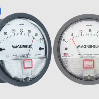
VCR’s published guidance generally associates the 0–500 Pa range with filter monitoring and the 0–60 Pa range with room differential pressure.
Comparison with 0–250 Pa
The 0–250 Pa model provides better pointer movement when the complete operating range remains below 250 Pa.
The 0–500 Pa model provides greater margin where filter pressure may rise above 250 Pa.
If a filter operates from approximately 100 Pa to a final limit below 200 Pa, a 0–250 Pa gauge may be easier to read.
Where the final pressure may reach 300–400 Pa, a 0–500 Pa gauge is more appropriate.
Comparison with 0–750 Pa
The 0–750 Pa range is more suitable for high-resistance filters, multiple filter stages or applications requiring additional margin.
The 0–500 Pa model provides better visual resolution when values remain below 500 Pa.
If the expected final resistance approaches 500 Pa, the 0–750 Pa model may provide safer margin.
If normal operation remains below 300 Pa, the 0–750 Pa range may be unnecessarily wide.
Comparison with 0–60 Pa
The 0–60 Pa model is primarily intended for low room-pressure measurement.
The 0–500 Pa model is more appropriate for HEPA filters, fine filters, AHUs, HEPA boxes and FFUs.
The two ranges should not be treated as interchangeable.
Supplied accessories
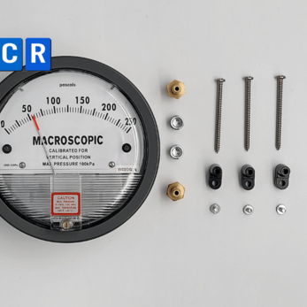
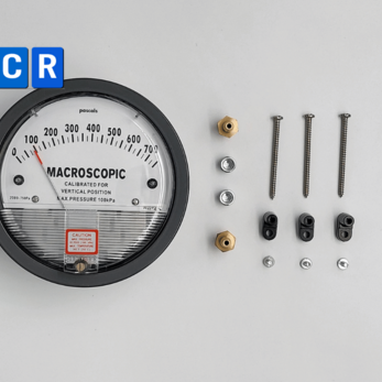
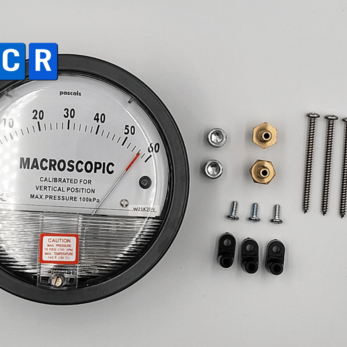
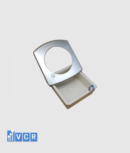
VCR’s product listing identifies the package as including the gauge, 1/8-inch NPT fittings, NPT blocks, rubber mounting feet and installation screws. The quotation should confirm whether pressure tubing, wall taps and a mounting enclosure are included.
Flexible tubing connects the High and Low pressure ports to the corresponding pressure-tapping locations. VCR describes this tubing as suitable for panel-mounted gauge installations.
Unused pressure ports should be sealed with suitable plugs.
Installation
Across a filter, the High port should connect upstream and the Low port downstream.
The gauge should be mounted vertically in a visible location and away from excessive vibration.
Pressure taps should represent static pressure and should not be positioned directly in high-velocity or turbulent airflow near fans and dampers.
Tubing should be airtight, free from kinks and protected from condensation.
High and Low lines should be clearly labelled.
The zero position should be checked after mounting but before the pressure tubes are connected.
Zero checking
A true zero condition exists only when the High and Low ports are at equal pressure.
Both tubes should normally be disconnected from the gauge so that both ports experience the same ambient pressure.
Stopping the fan while leaving the tubing connected may leave pressure trapped in the plenum or filter housing.
If the pointer returns to zero after disconnection, the instrument is probably functioning and the problem is associated with the tubing, pressure taps or actual system pressure.
Zero adjustment does not replace calibration.
Calibration
Calibration compares the indicated value with a traceable differential-pressure reference.
Test points should cover the actual operating region and several parts of the range. A test programme may include 0, 100, 200, 300, 400 and 500 Pa, subject to project requirements.
Increasing and decreasing pressure tests can be used to evaluate hysteresis.
The calibration certificate should identify the instrument, serial or asset number, range, units, method, reference equipment, reference values, displayed values, errors, measurement uncertainty and acceptance conclusion.
GMP suitability
The Macroscopic 0–500 Pa gauge may be used in a GMP facility when it is suitable for the intended measurement, operating range, acceptance tolerance and equipment-control programme.
GMP suitability is not established by the brand name or CO/CQ documents alone.
The facility should demonstrate correct range selection, proper installation, calibration, identification, periodic inspection and technically justified filter limits.
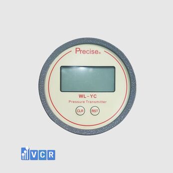
Where continuous alarms and electronic records are required, the mechanical gauge should be supplemented by an electronic transmitter with 4–20 mA, 0–10 V or Modbus output.
Advantages
The 0–500 Pa range is suitable for many cleanroom filter and HVAC applications.
The instrument requires no electrical supply and remains available for direct local inspection.
The mechanical dial allows operators to quickly observe increasing filter resistance.
Published accuracy is ±2% of full scale at 21°C. The product is also supplied with installation fittings according to VCR’s product description.
The range provides more operating margin than a 0–250 Pa gauge for filters with relatively high final resistance.
Limitations
The standard mechanical model does not provide an electrical output, remote alarm or historical records.
The 0–500 Pa range is too wide for most low room-pressure applications.
Its published full-scale accuracy corresponds to approximately ±10 Pa, which should be assessed carefully where the normal operating value is low.
Readings depend on airflow, fan speed, tubing integrity and pressure-tap location.
The gauge does not replace HEPA leak testing, airflow measurement or airflow visualisation.
When should this model be selected?
The Macroscopic 0–500 Pa gauge should be considered where the maximum expected pressure remains below 500 Pa and the normal operating region remains clearly visible on the dial.
Typical applications include HEPA filters, bag filters, fine filters, AHUs, HEPA boxes, FFUs, laminar airflow units, dynamic pass boxes and air showers.
A lower range should be selected for low room-pressure measurement.
A 0–750 Pa model should be considered where the final pressure may approach or exceed 500 Pa.
Purchasing checks
Before ordering, confirm the Macroscopic brand, 0–500 Pa scale and Pa units.
Check the pointer, dial cover, zero adjustment, High and Low ports and supplied fittings.
The quotation should state whether tubing, pressure taps, mounting enclosure, CO, CQ, calibration, VAT and warranty are included.
For projects with several gauges, prepare an instrument schedule showing the location, measurement purpose and required range for each point.
Frequently asked questions
What is the main application?
The gauge is mainly used to monitor HEPA filters, bag filters, fine filters and AHU filter stages.
Can it monitor cleanroom pressure?
It can, but the range is normally too wide when room pressure is only a few tens of pascals.
Can it be used for HEPA filters?
Yes, when the complete clean-to-final pressure range remains within 0–500 Pa.
Does it require electrical power?
No. The basic pointer indication is mechanical.
Does it provide 4–20 mA output?
The standard model does not. A separate electronic transmitter is required.
What is the published accuracy?
The published accuracy is ±2% of full scale at 21°C, equivalent to approximately ±10 Pa for the 0–500 Pa range.
Is 500 Pa the filter replacement point?
No. The replacement limit should be established from the filter datasheet, design airflow, fan capability and approved system criteria.
Does zero adjustment replace calibration?
No. Zero adjustment verifies one point, while calibration verifies accuracy at multiple points across the range.
Conclusion
The Macroscopic 0–500 Pa differential pressure gauge is suitable for many filter-loading and HVAC monitoring applications in cleanroom systems.
Its range provides greater operating margin than the 0–250 Pa model while offering better visibility than a 0–750 Pa instrument when operating pressure remains below 500 Pa.
The gauge requires no electrical supply and provides direct local indication. It is generally not suitable for low room-pressure measurements.
Reliable operation depends on correct High and Low connections, representative static-pressure taps, airtight tubing, zero checking and periodic calibration.
For GMP or critical applications, the instrument should be identified, calibrated and included in the approved inspection programme. An electronic transmitter should be added where alarms, data logging or central monitoring are required.
VCR Cleanroom Equipment supplies Macroscopic 0–500 Pa differential pressure gauges, installation accessories, documentation and calibration solutions for HEPA filters, AHUs, HEPA boxes, FFUs, laminar airflow units, pass boxes, air showers and cleanroom HVAC systems. VCR also supports range selection, pressure-tap arrangement and project commissioning.