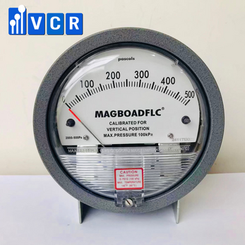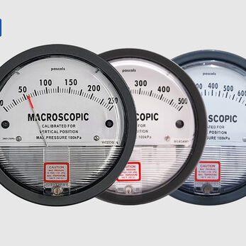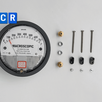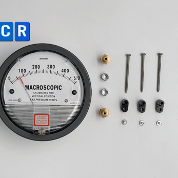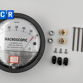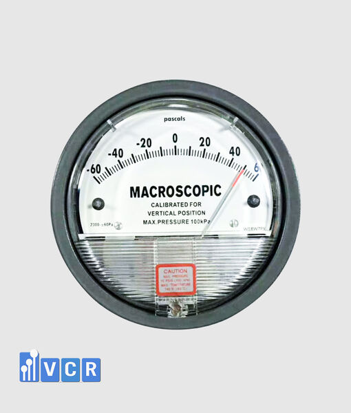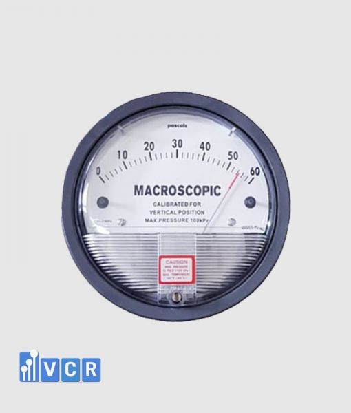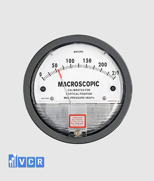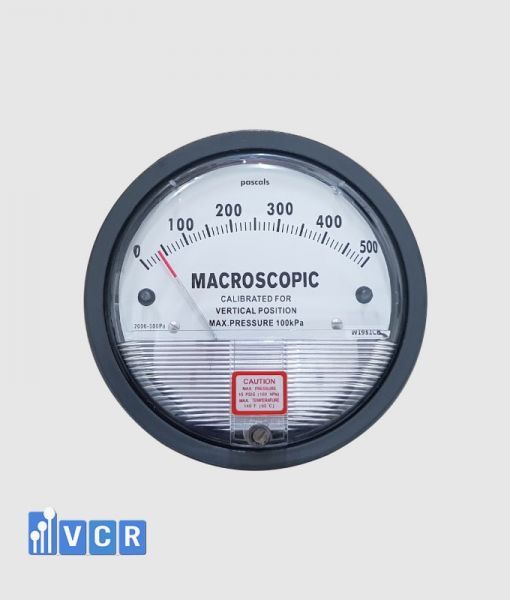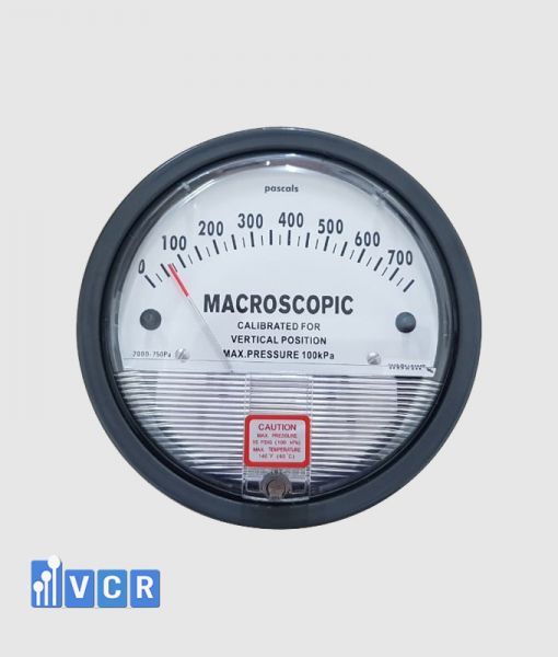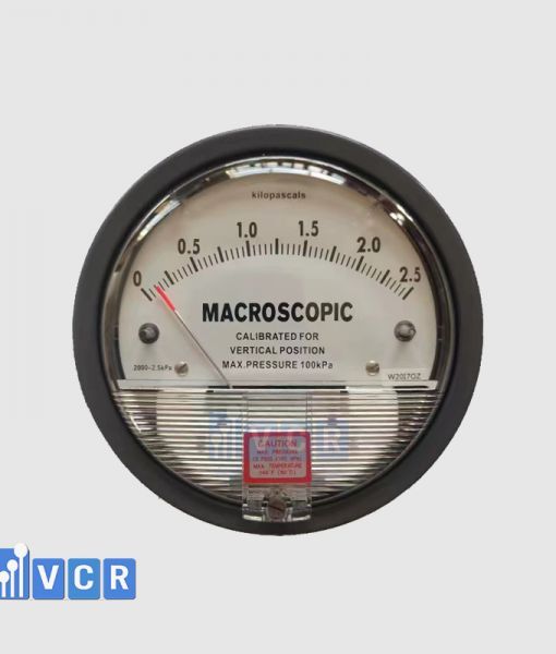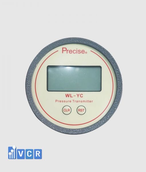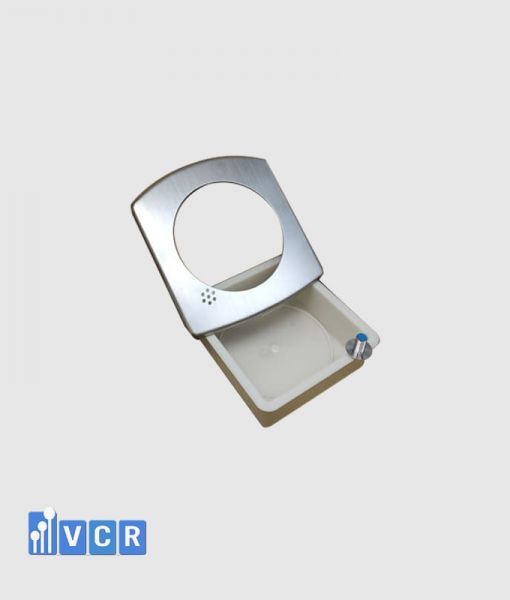

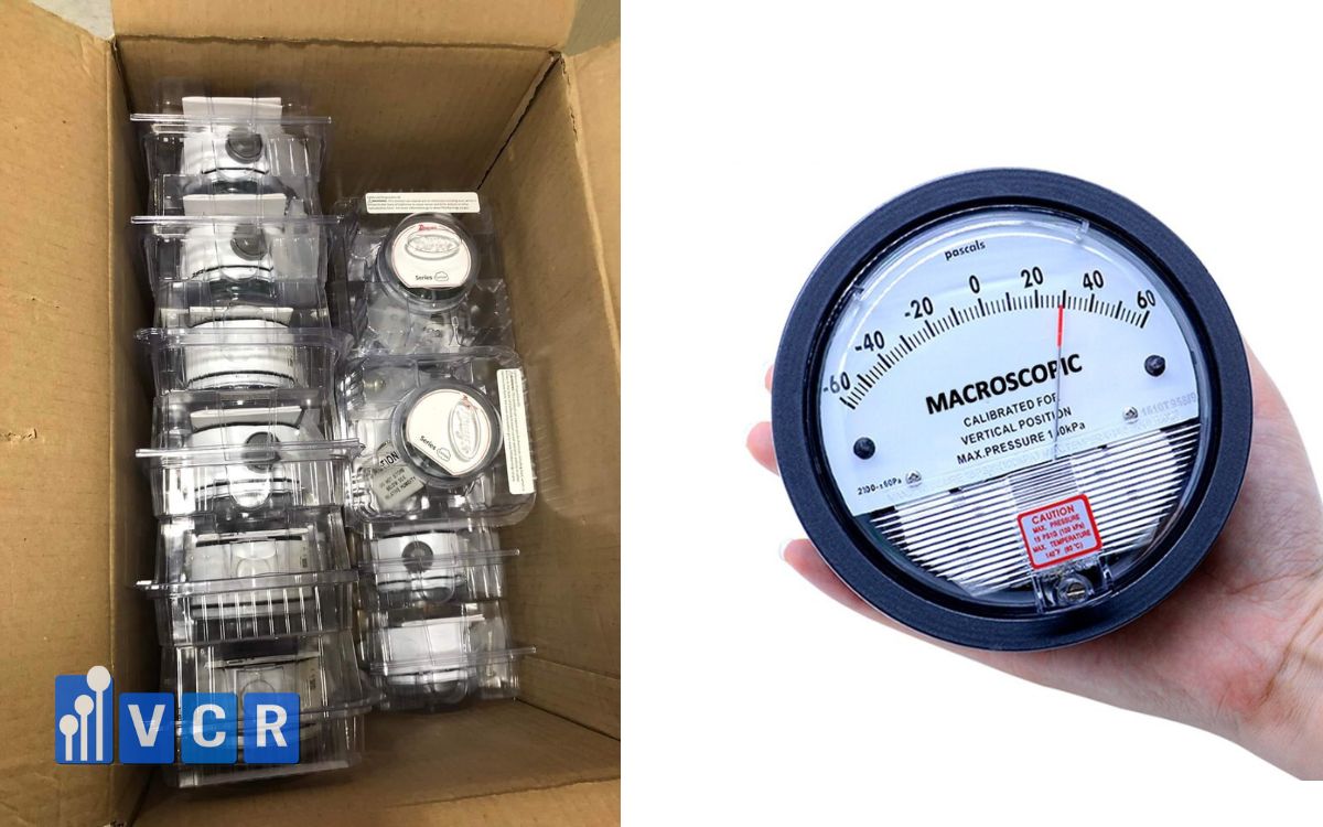
A mechanical differential pressure gauge displays the pressure difference between two points using an analogue pointer. It is widely used to monitor cleanroom pressure, HEPA filter loading, AHU filters and HVAC system operating conditions.
- What is a mechanical differential pressure gauge?
- What is the gauge used for?
- Main components of a mechanical differential pressure gauge
- Operating principle
- Advantages of a mechanical differential pressure gauge
- Limitations of a mechanical differential pressure gauge
- Mechanical versus electronic differential pressure gauges
- How to select a mechanical differential pressure gauge
- Basic installation guidance
- Inspection and calibration
- Common faults and troubleshooting
- Frequently asked questions
- Does a mechanical differential pressure gauge require electricity?
- Can a mechanical gauge be used in a GMP cleanroom?
- Can one gauge model be used for both room pressure and HEPA filters?
- Can a mechanical gauge provide an automatic filter alarm?
- How often should the gauge be calibrated?
- Does zero adjustment replace calibration?
- Conclusion
What is a mechanical differential pressure gauge?
A mechanical differential pressure gauge is an instrument that measures and displays the pressure difference between two locations in a system.
The measured value is indicated by a pointer moving across a graduated analogue dial. The instrument is therefore also known as an analogue differential pressure gauge, needle differential pressure gauge or mechanical DP gauge.

Other application-based names include:
- Cleanroom differential pressure gauge.
- HEPA filter differential pressure gauge.
- Filter pressure-drop gauge.
- Filter clogging indicator.
- AHU differential pressure gauge.
- Mechanical pressure-difference indicator.
Unlike a conventional pressure gauge, which measures pressure at one location relative to a reference, a differential pressure gauge compares two pressure points.
The basic measurement is:
Differential pressure = High-port pressure − Low-port pressure
The High or positive port is connected to the higher-pressure location, while the Low or negative port is connected to the lower-pressure location.
What is the gauge used for?
In cleanroom and HVAC applications, mechanical differential pressure gauges are mainly used for room-pressure monitoring and filter-pressure-drop monitoring.
For room monitoring, the gauge may compare the pressure inside a cleanroom with the pressure in an adjacent corridor or another controlled room. The indication helps operators confirm the intended pressure cascade and airflow direction.
For filter monitoring, the High port is connected upstream of the filter and the Low port downstream. As particles accumulate on the filter media, airflow resistance generally increases, causing the displayed differential pressure to rise at a similar airflow rate.
Typical applications include:
- Cleanroom pressure monitoring.
- HEPA filter loading indication.
- AHU pre-filter and bag-filter monitoring.
- HEPA box monitoring.
- Dynamic pass box filter monitoring.
- Air shower pressure-drop monitoring.
- FFU filter condition monitoring.
- Dispensing booth and sampling booth monitoring.
- Coil pressure-drop measurement.
- Duct and ventilation-system monitoring.
- Laboratory and process equipment.
Main components of a mechanical differential pressure gauge
The exact design varies between manufacturers, but most mechanical gauges contain several common elements.
Gauge housing
The housing protects the sensing element and transmission mechanism. Materials may include die-cast aluminium, steel, engineering plastic or stainless steel.
For cleanroom installation, the front surface is often designed for flush mounting and easy cleaning.
Analogue dial
The dial contains a graduated measuring scale. Common units include Pa, kPa, mmH₂O and in.w.c.
Some gauges have dual scales. Coloured operating zones or adjustable limit markers may also be included to identify normal, warning and action ranges.
Pointer
The pointer moves in response to differential pressure. Its length and design should make the value easy to read from a practical viewing distance.
Pressure-sensing element
The sensing element responds to the difference between the High and Low ports. Depending on the design, it may use a diaphragm, capsule, flexible membrane or magnetic sensing mechanism.
Transmission mechanism
The transmission mechanism converts the small displacement of the sensing element into rotary movement of the pointer.
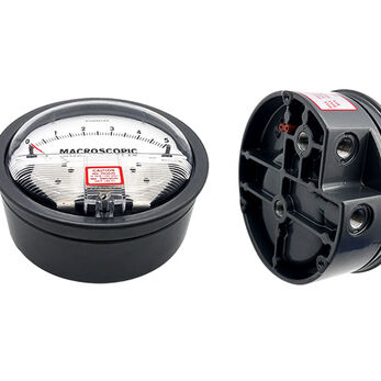
High and Low pressure ports
The High port is normally marked with “+”, while the Low port is marked with “−”. These ports are connected to the measurement locations using flexible tubing or rigid pressure lines.
Zero-adjustment mechanism
Many gauges include a front-accessible zero-adjustment screw.
Zero adjustment allows the pointer to be aligned with zero when both ports are at equal pressure. It does not replace a full calibration of the instrument.
Operating principle
Pressure from the two measurement locations is transmitted to the gauge through pressure tubing.
When the High-port pressure exceeds the Low-port pressure, the internal sensing element deflects or moves. The displacement is transferred to the pointer through a mechanical or magnetic mechanism.
The pointer stops at the dial position corresponding to the measured pressure difference.
For HEPA filter monitoring:
- The High port is connected upstream of the filter.
- The Low port is connected downstream.
- A clean filter produces its initial operating pressure drop.
- As dust accumulates, resistance increases and the pointer moves to a higher value.
For room-pressure monitoring:
- The High port is connected to the room designed to operate at higher pressure.
- The Low port is connected to the lower-pressure room or corridor.
- The gauge displays the actual pressure difference between the spaces.
If the two ports are reversed, the pointer may move in the negative direction, move below zero or indicate incorrectly depending on the gauge design.
Advantages of a mechanical differential pressure gauge
No external power is normally required
Most mechanical gauges operate through a mechanical or magnetic pressure-sensing mechanism and do not require an electrical power supply.
The pressure value remains locally visible without relying on a PLC, HMI or communication network.
Clear local indication
The analogue pointer provides a quick visual indication of the current operating condition.
When limit markers or coloured zones are used, an operator can rapidly identify whether the pressure is normal, approaching a warning condition or outside the acceptable range.
Relatively simple construction
The gauge has no complex electronic display, software or communication module.
Installation, basic operation and routine inspection are therefore relatively straightforward.
Cost-effective monitoring
Mechanical gauges normally cost less than electronic transmitters or digital monitoring systems.
They are particularly suitable where only a local reading is required and there is no need for automatic recording or remote transmission.
Suitable for low differential pressure
Many models are designed for low-pressure ranges used in cleanrooms and filtration systems.
These ranges may cover only a few tens or hundreds of pascals, allowing the instrument to show small pressure differences clearly.
Suitable for flush mounting
Mechanical gauges can often be installed flush with cleanroom wall panels, equipment housings or AHU panels.
Flush mounting produces a neat appearance, protects the instrument and makes it convenient for routine observation.
Independent of the control system
A mechanical gauge is not affected by PLC software faults, communication failures or HMI screen problems.
The operator can obtain a direct local indication even if the central monitoring system is unavailable.
Broad range of applications
The same measurement principle can be used for cleanroom pressure, HEPA filters, AHU filters, coils, ducts, fans and process equipment.
Limitations of a mechanical differential pressure gauge
No standard remote output
A basic mechanical gauge only provides a local indication. It does not automatically transmit the measurement to a PLC, BMS, HMI or environmental monitoring system.
A differential pressure transmitter or electronic gauge is required when remote monitoring is needed.
No automatic data logging
The gauge does not normally store historical readings.
Operators must manually record the values in a logbook, checklist or electronic maintenance system. Manual recording may introduce omissions, transcription errors and inconsistent monitoring intervals.
Limited alarm capability
Most standard mechanical gauges do not include relay outputs, buzzers or warning lights.
Some specialised models offer electrical contacts, but their alarm configuration is usually less flexible than that of digital instruments.
Potential reading error
The reading may be affected by the viewing angle. Looking at the dial from one side can create parallax error.
Measurement resolution is also limited by the dial graduation and the operator’s ability to estimate values between scale marks.
Pointer fluctuation
The pointer may oscillate when the pressure is unstable, doors are opened, fan speed changes or the pressure tapping point is exposed to turbulence.
Excessive fluctuation makes accurate reading more difficult.
Limited suitability for automatic control
Systems that automatically regulate fan speed, operate dampers, activate interlocks or generate alarms need an electrical signal.
A basic mechanical gauge cannot directly provide the signal required for automatic control.
Possible zero drift
After extended operation, the pointer may not return exactly to zero when both ports are at equal pressure.
Possible causes include installation orientation, vibration, ageing of the mechanism or mechanical shock.
Dependence on pressure tubing condition
Kinked, leaking, disconnected or blocked pressure tubing can produce an incorrect reading.
Condensation inside the tubing may also affect pressure transmission. In many cases, an apparent instrument fault is actually caused by the tubing or tapping points.
No automatic airflow compensation
Filter pressure drop varies with airflow. If fan speed changes, the gauge value may change even when the filter condition remains unchanged.
Filter-loading trends should therefore be compared at similar operating airflow conditions.
Mechanical versus electronic differential pressure gauges
Mechanical gauges are suitable where the main requirement is a simple local display, low installation cost and operation without power.
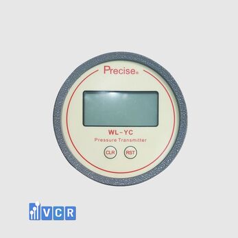
Electronic gauges are preferable where the system requires remote communication, data logging, configurable alarms or automatic control.
| Criterion | Mechanical gauge | Electronic gauge |
|---|---|---|
| Display | Analogue pointer | Digital screen |
| Power supply | Normally not required | Required |
| Remote output | Normally unavailable | Often available |
| Alarm configuration | Limited | Flexible |
| Data logging | Not available | May be available |
| Local readability | Good | Good |
| Initial cost | Usually lower | Usually higher |
| PLC/BMS integration | Limited | Suitable |
| Resolution | Based on scale marks | Usually higher |
Neither type is universally superior. Selection should reflect the criticality of the measurement point and the intended monitoring strategy.
How to select a mechanical differential pressure gauge
Define the application
First determine whether the gauge will monitor room pressure or filter pressure drop.
Room-pressure applications typically require a low range with fine resolution. Filter monitoring requires a range that covers the clean-filter pressure drop and the expected final operating resistance.
Select the correct measuring range
The full-scale range should exceed the maximum expected differential pressure, but it should not be unnecessarily wide.
A range that is too wide makes small changes difficult to observe. A range that is too narrow may cause the pointer to exceed full scale during abnormal operation.
A gauge with a range of several thousand pascals would generally provide poor resolution for a room pressure of only a few tens of pascals.
Review the accuracy specification
Accuracy should match the application and the facility’s measurement requirements.
Important cleanroom, GMP and acceptance-test points should be selected according to defined accuracy criteria rather than dial size alone.
Select the measuring unit
Pa is commonly used in cleanroom applications. Imported instruments may use mmH₂O or in.w.c.
The unit should be consistent with drawings, SOPs, alarm limits, qualification documents and other instruments in the facility.
Review materials and mounting arrangement
Important considerations include:
- Flush or surface mounting.
- Dial diameter.
- Housing material.
- Resistance to dust and moisture.
- Surface-cleaning requirements.
- Approved installation orientation.
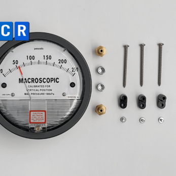
- Supplied tubing and fittings.
- Environmental temperature and humidity.
Determine calibration requirements
For critical measurement points, the gauge should have a clear calibration route and appropriate technical documentation.
The purchaser should confirm whether the supplier can provide calibration certificates, identification labels and traceable records.
Basic installation guidance
For filter monitoring, connect the High port upstream and the Low port downstream.
For room monitoring, connect the High port to the higher-pressure room and the Low port to the lower-pressure room or corridor.
Pressure tubing should be:
- Airtight.
- Free from kinks or compression.
- Protected from condensation.
- Clearly identified as High and Low.
- Installed away from excessive turbulence.
- Checked before commissioning.
The gauge must be installed in the manufacturer’s approved orientation. Its zero position should be checked after installation while both ports are at equal pressure.
Inspection and calibration
Visual inspection should confirm the condition of the dial, pointer, window, pressure connections, mounting and zero-adjustment mechanism.
Functional testing may be performed by applying known differential pressure values using a reference calibrator and comparing the gauge indication with the reference.
Testing should cover multiple points across the range, including low, middle and upper values. The ability of the pointer to return to zero should also be verified.
For GMP systems and critical points, the results should be documented and testing should follow an approved periodic schedule.
Common faults and troubleshooting
The pointer does not return to zero
The gauge may require zero adjustment, may be installed in the wrong orientation or may still have trapped pressure in the tubing.
Mechanical drift or damage is also possible.
The pointer does not move
Possible causes include disconnected tubing, leakage, blockage, incorrect tapping points or the absence of an actual pressure difference.
The gauge displays a negative value
The High and Low connections may have been reversed.
The pointer fluctuates excessively
Possible causes include unstable airflow, an unsuitable pressure tapping location, fan-speed variation or mechanical vibration.
The reading is unexpectedly low
Potential causes include reduced fan speed, leakage, filter bypass, poor filter sealing or incorrect airflow.
The reading is unexpectedly high
In addition to a loaded filter, the operator should inspect dampers, ducts, pressure tapping points and actual airflow.
Frequently asked questions
Does a mechanical differential pressure gauge require electricity?
Most models do not require power for basic indication. Models with electrical contacts or warning lights may require an electrical connection.
Can a mechanical gauge be used in a GMP cleanroom?
Yes, provided that the measuring range, accuracy, cleanability, calibration status and documentation meet the project requirements.
Can one gauge model be used for both room pressure and HEPA filters?
The operating principle may be the same, but the required ranges and resolutions are often different. Each application should be evaluated separately.
Can a mechanical gauge provide an automatic filter alarm?
A basic model only provides visual indication. Automatic alarming requires a gauge with contacts, a pressure switch or an electronic differential pressure transmitter.
How often should the gauge be calibrated?
The interval depends on the facility quality system, measurement criticality, operating conditions and maintenance programme.
Does zero adjustment replace calibration?
No. Zero adjustment only aligns the pointer when differential pressure is zero. Calibration verifies accuracy at several points across the measuring range.
Conclusion
A mechanical differential pressure gauge is a simple, visible and cost-effective solution for monitoring pressure differences in cleanrooms, HVAC systems and air-filtration equipment.
Its main advantages include operation without external power, clear local indication, simple construction and suitability for low-pressure applications.
Its limitations include the lack of standard remote communication, automatic alarms, historical data storage and direct integration with control systems.
Successful selection requires the correct measuring range, accuracy, unit, mounting arrangement, environmental suitability and calibration strategy. A correctly selected and installed gauge provides much more reliable monitoring than an instrument chosen only on the basis of purchase price.
VCR Cleanroom Equipment supplies mechanical differential pressure gauges for cleanrooms, AHUs, HEPA boxes, pass boxes, air showers, FFUs, laminar airflow units and dispensing booths. VCR also supports measuring-range selection, installation accessories, technical documentation, calibration and project commissioning.