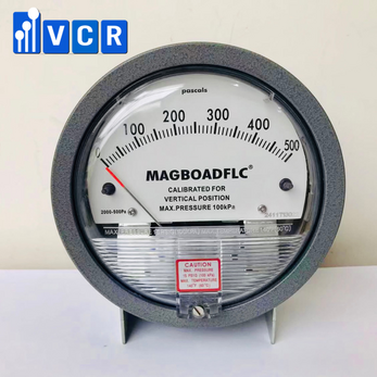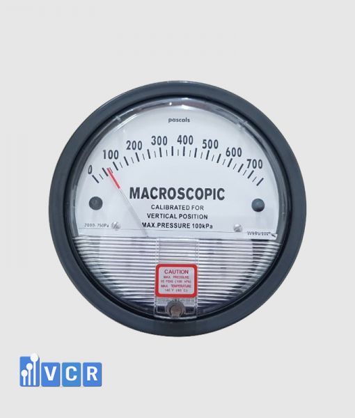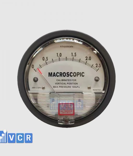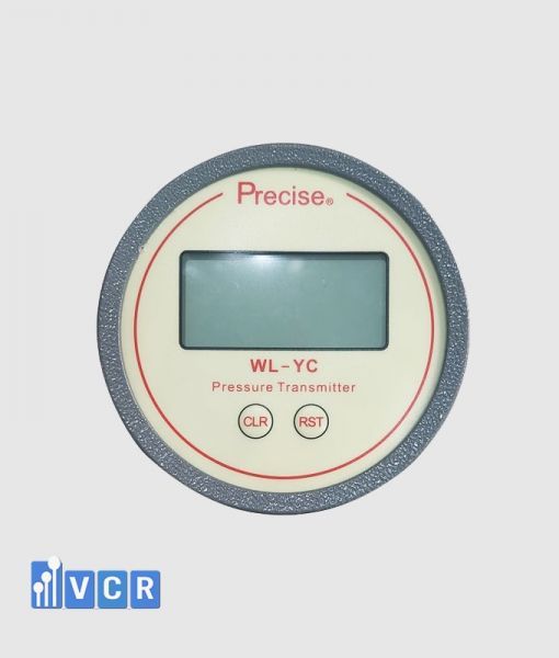

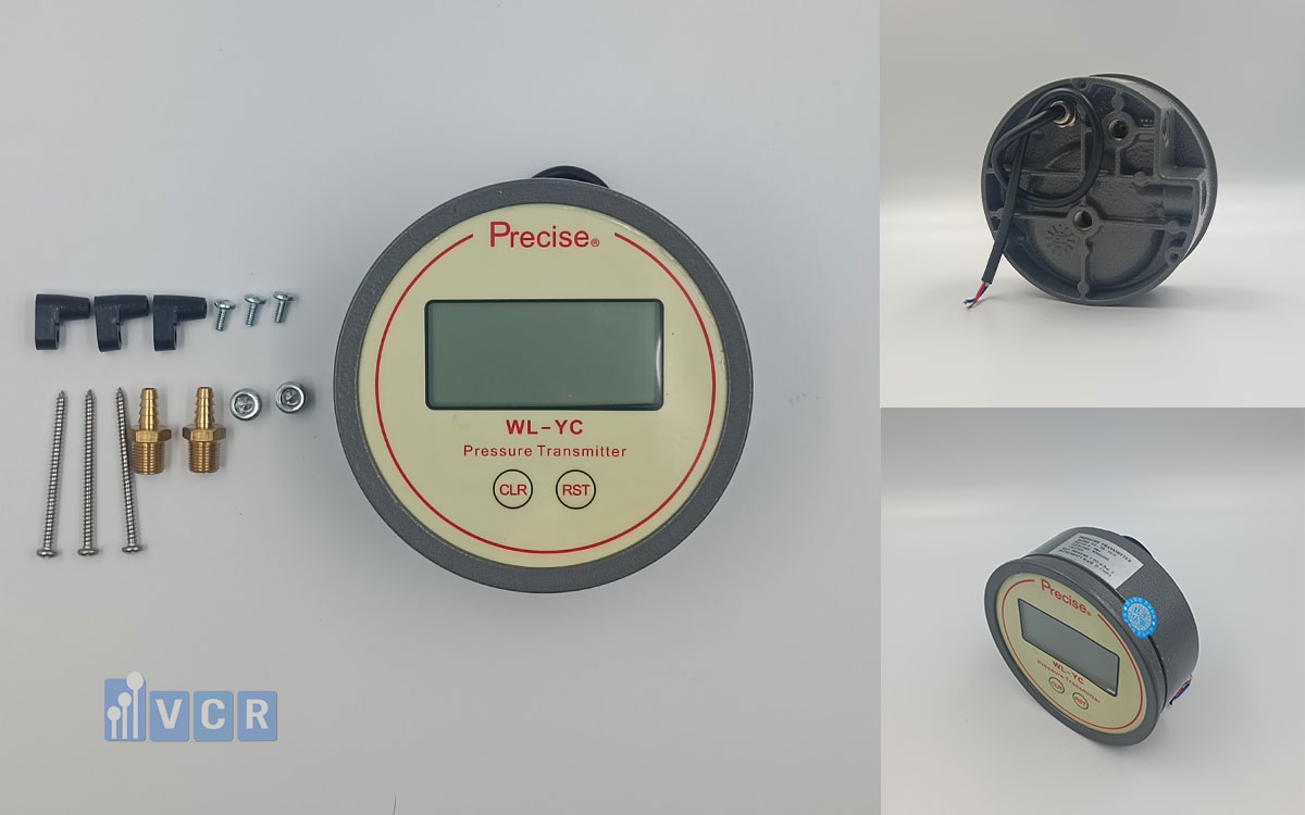
Acceptance testing of a differential pressure gauge with a 4–20 mA output must cover the pressure measurement, current signal, wiring, power supply, configured range, PLC, HMI, BMS, alarms, and fault conditions. Checking only the value displayed locally on the gauge is not sufficient.
- What Is a Differential Pressure Gauge with a 4–20 mA Output?
- Why Must the Entire 4–20 mA Measurement Loop Be Tested?
- What Should Be Prepared Before Acceptance Testing?
- Review the Documentation and Device Identification
- Inspect the Physical Condition and Installation Location
- Check the High-Pressure and Low-Pressure Ports
- Inspect the Pressure Tubing
- Check the Power Supply
- Check the Current Loop Load Resistance
- Inspect the Signal Wiring
- Verify LRV and URV Configuration
- Formula for Converting a 4–20 mA Signal
- Perform a 4–20 mA Loop Test
- Can a Loop Test Replace a Pressure Test?
- Test the Complete Measurement Chain Using Reference Pressure
- What Values Should Be Recorded at Each Test Point?
- How Should the Acceptance Tolerance Be Defined?
- Check the Zero Point
- Test the Alarm Setpoints
- Test the Signal Fault Conditions
- Test Power Loss and Open-Circuit Conditions
- Check the Signal Direction
- Check Response Time and Damping
- Check Stability and Repeatability
- Check HART or Digital Communication When Provided
- What Documents Should Be Included in the Acceptance Package?
- Suggested Acceptance Criteria
- Common Problems During Acceptance Testing
- What Risks Arise If the Transmitter Remains in Loop Test Mode?
- What Information Should Be Provided When Purchasing from VCR Cleanroom Equipment?
- Conclusion
- FAQ: Acceptance Testing of Differential Pressure Gauges with 4–20 mA Output
- Which Points Should Be Tested on a 4–20 mA Differential Pressure Gauge?
- Is a Loop Test Sufficient for Acceptance?
- Why Does the PLC Display the Wrong Value When the Signal Is 12 mA?
- Should Fault Signals Below 4 mA or Above 20 mA Be Tested?
- What Is the Acceptable Error for a 4–20 mA Measurement Loop?
- What Documents Are Required for a 4–20 mA Differential Pressure Gauge in a GMP Project?
- Contact VCR Cleanroom Equipment
What Is a Differential Pressure Gauge with a 4–20 mA Output?
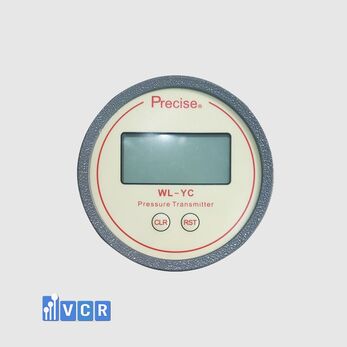
A differential pressure gauge with a 4–20 mA output is a device that measures differential pressure and converts the measured value into a current signal for transmission to a PLC, HMI, BMS, controller, or centralized monitoring system.
Depending on the design and manufacturer, the device may also be called:
Electronic differential pressure gauge.
Differential pressure sensor.
Differential pressure transmitter.
Differential pressure sensor with display.
Differential pressure gauge with a 4–20 mA output.
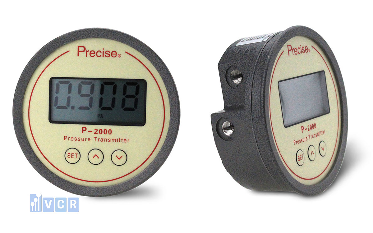
In a typical linear configuration, the lowest value of the configured range corresponds to 4 mA, while the highest value corresponds to 20 mA.
For example, if the device is configured for a range of 0–100 Pa:
0 Pa corresponds to 4 mA.
25 Pa corresponds to 8 mA.
50 Pa corresponds to 12 mA.
75 Pa corresponds to 16 mA.
100 Pa corresponds to 20 mA.
Because this signal is used for remote monitoring, alarm generation, and sometimes automatic control, acceptance testing must evaluate the entire measurement loop rather than only the local display.
Why Must the Entire 4–20 mA Measurement Loop Be Tested?
A differential pressure measurement loop generally includes:
Pressure pickup points.
Pressure tubing.
High-pressure and low-pressure ports.
Differential pressure sensor.
Signal conversion circuit.
Power supply.
Signal cable.
Terminal blocks.
PLC or BMS analog input module.
Signal processing software.
HMI display.
Alarm thresholds.
Data logging and trend storage.
A problem in any part of this chain may cause the displayed value to differ from the actual differential pressure.
For example, the sensor may measure correctly while the PLC is configured with the wrong range. The local display may also be correct while the HMI receives an inaccurate value because of incorrect scaling, wiring resistance, polarity, or analog input configuration.
Acceptance testing should therefore confirm three essential functions:
The device measures differential pressure correctly.
The device outputs the correct 4–20 mA signal.
The PLC, HMI, or BMS converts the signal into the correct pressure value.
What Should Be Prepared Before Acceptance Testing?
Technical documentation and suitable test instruments should be prepared before starting the test.
Recommended documents include:
Product catalogue or datasheet.
Installation and operating manual.
Wiring diagram.
Loop diagram.
Installation drawing.
I/O list.
PLC or BMS configuration table.
Designed measuring range.
Unit of measurement.
Alarm setpoints.
Accuracy requirements.
Calibration certificate.
Factory inspection report, when available.
Recommended test equipment may include:
Differential pressure calibrator.
Low-pressure generator.
Reference pressure measuring instrument.
Milliamp meter.
Digital multimeter.
4–20 mA signal simulator.
Suitable DC power supply.
HART communicator, when supported.
Computer with PLC or BMS configuration software.
The reference equipment used during acceptance testing should have a valid calibration status appropriate to the project requirements.
For GMP facilities, instruments used for measurement, recording, and control should be calibrated and checked at defined intervals using suitable methods, with appropriate records retained.
Review the Documentation and Device Identification
The first step is to compare the installed device with the approved technical documentation.
The following information should be checked:
Manufacturer.
Brand.
Model.
Serial number.
Sensor measuring capability.
Configured measuring range.
Unit of measurement.
Power supply.
Output signal.
Number of connection wires.
Ingress protection rating.
Accuracy.
Operating temperature and humidity.
Project equipment identification number.
Installation location.
The device nameplate should match the catalogue, purchase order, approved drawings, equipment schedule, and technical specification.
Particular attention should be paid to the difference between the sensor’s maximum measuring capability and its configured output range.
For example, a sensor may be capable of measuring 0–250 Pa but be configured so that 4–20 mA represents only 0–100 Pa. In this case, the PLC must be scaled for 0–100 Pa, not 0–250 Pa.
Inspect the Physical Condition and Installation Location
The physical condition and mounting arrangement should be checked before electrical or functional testing.
The inspection should confirm that:
The housing is not cracked or deformed.
The display is not damaged.
The nameplate is legible.
Electrical terminals are properly protected.
Pressure connections are secure.
There is no evidence of water or moisture ingress.
The device is firmly mounted.
The mounting direction follows the manufacturer’s instructions.
Adequate space is available for maintenance and calibration.
The device is not installed in an area with excessive vibration.
The device is not exposed to temperatures outside its rated limits.
For certain differential pressure transmitters, the mounting position can affect the zero point. The final mechanical installation should therefore be completed before zero adjustment or on-site calibration is performed.
Check the High-Pressure and Low-Pressure Ports
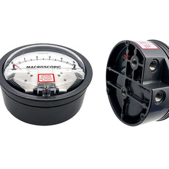
A differential pressure device normally has two pressure connections:
The High port or plus symbol is the high-pressure connection.
The Low port or minus symbol is the low-pressure connection.
When measuring differential pressure between two rooms, the High port should be connected to the room with higher pressure, while the Low port should be connected to the room with lower pressure.
If the pressure ports are reversed, the system may:
Display a negative value.
Indicate pressure in the wrong direction.
Activate a low-pressure alarm.
Record incorrect data in the BMS.
Cause an incorrect assessment of cleanroom pressure conditions.
During acceptance testing, both ends of each pressure tube should be traced and identified to ensure that the High and Low connections have not been crossed.
Inspect the Pressure Tubing
Pressure tubing directly affects the accuracy and response of the measurement.
The inspection should confirm that the tubes are:
Not kinked.
Not flattened.
Not cracked.
Not loosely connected.
Free from leakage.
Free from dust blockage.
Free from condensate.
Properly routed.
Securely fixed.
Protected from physical damage.
Separated from heat sources that may deform the tubing.
If one pressure tube is blocked or leaking, the gauge may respond slowly, fail to return to zero, or display an incorrect value.
When the pressure at the High and Low ports is equalized, the reading should return close to zero within the permitted tolerance.
If the value does not return to zero, the pressure tubing, leakage, mounting position, zero setting, and sensor condition should be investigated.
Check the Power Supply
A differential pressure transmitter with a 4–20 mA output may use a 24 VDC power supply or another voltage specified by the manufacturer.
The following should be measured during acceptance testing:
Voltage at the power supply.
Voltage at the device terminals.
Positive and negative polarity.
Voltage available when the output approaches 20 mA.
Power supply stability.
Whether the power supply is shared with other devices.
Grounding and shielding arrangements, when required.
The voltage should not be checked only at the control panel. It should also be measured directly at the transmitter terminals because voltage drop may occur across cables, terminal blocks, signal isolators, or protection devices.
The permitted supply voltage and load resistance depend on the specific model. The manufacturer’s datasheet should therefore be used instead of applying one general value to every transmitter.
Check the Current Loop Load Resistance
A 4–20 mA loop operates correctly only when the power supply provides sufficient voltage for:
The transmitter.
Signal cable resistance.
PLC input resistance.
Signal isolators.
Additional indicators.
HART communication resistance, when applicable.
Any other devices connected in series.
If the total loop resistance is too high, the transmitter may be unable to reach 20 mA, particularly at the upper end of the measuring range.
The acceptance report should record:
Measured supply voltage.
Estimated total loop load.
Input resistance of the analog module.
Devices connected in series.
Measured output at 4 mA.
Measured output at 20 mA.
Inspect the Signal Wiring
The wiring should be checked against the approved diagram and the actual transmitter type.
Common transmitter configurations include:
Two-wire transmitter.
Three-wire transmitter.
Four-wire transmitter.
Active current output.
Passive current output.
Isolated output.
Non-isolated output.
The inspection should confirm:
Correct positive and negative polarity.
Correct power terminals.
Correct output terminals.
Connection to the correct analog input channel.
No accidental connection to a digital input.
Cable shielding is grounded according to the design.
The shield is not grounded at multiple points unless specifically required.
Signal cables are separated from power cables.
Cable lugs are properly crimped.
Wire numbers match the drawings.
Terminal blocks are clearly labelled.
If the polarity is reversed, some transmitters will not operate. If the signal is connected to an incorrect test terminal or module terminal, the current may not be transmitted correctly to the PLC.
Verify LRV and URV Configuration
LRV means Lower Range Value, which is the value assigned to 4 mA.
URV means Upper Range Value, which is the value assigned to 20 mA.
For example:
LRV = 0 Pa.
URV = 100 Pa.
Therefore:
0 Pa = 4 mA.
100 Pa = 20 mA.
For a bidirectional range of −50 Pa to +50 Pa:
−50 Pa = 4 mA.
0 Pa = 12 mA.
+50 Pa = 20 mA.
The LRV and URV should be verified in:
The transmitter.
The transmitter configuration software.
The PLC.
The HMI.
The BMS.
The I/O list.
The calibration certificate or configuration record.
If the transmitter is configured for 0–100 Pa while the PLC is configured for 0–250 Pa, a 12 mA signal represents 50 Pa at the transmitter but may be displayed as 125 Pa by the PLC.
This is a common configuration error that may not be detected by checking only the local display.
Formula for Converting a 4–20 mA Signal
For a linear signal, the output current can be calculated using:
I = 4 + 16 × (P − LRV) / (URV − LRV)
Where:
I is the output current in mA.
P is the differential pressure value.
LRV is the lowest configured value.
URV is the highest configured value.
The pressure value can be calculated from the current using:
P = LRV + (I − 4) × (URV − LRV) / 16
For example, if the configured range is 0–100 Pa and the measured current is 10.4 mA:
P = 0 + (10.4 − 4) × 100 / 16
P = 40 Pa.
This formula should be used to verify the scaling logic in the PLC or BMS.
Perform a 4–20 mA Loop Test
A loop test forces the transmitter to output a fixed current value independently of the actual pressure.
Typical test values include:
4 mA.
8 mA.
12 mA.
16 mA.
20 mA.
Some transmitters also allow low-fault and high-fault current values to be simulated.
The purpose of the loop test is to verify that:
The transmitter analog output operates correctly.
The signal cable is continuous.
The polarity is correct.
The analog input module reads the signal correctly.
The PLC converts the signal correctly.
The HMI displays the correct value.
The BMS receives the correct data.
The data logger operates correctly.
Alarm logic processes the signal correctly.
At each simulated current, the expected pressure value should be calculated and compared with the PLC, HMI, and BMS displays.
Can a Loop Test Replace a Pressure Test?
No.
A loop test checks only the electrical output and the signal processing system after the transmitter’s sensor conversion stage. It does not prove that the pressure sensor is measuring accurately.
For example, a transmitter with a damaged or drifting pressure sensor may still output accurate forced values of 4 mA, 12 mA, and 20 mA during a loop test.
The PLC may therefore display the correct values during the loop test while the transmitter still produces inaccurate results during normal measurement.
A complete acceptance procedure must include both:
A 4–20 mA loop test.
A pressure simulation test using a calibrated pressure reference.
Test the Complete Measurement Chain Using Reference Pressure
This is the most important test for evaluating the complete chain from pressure input to the value displayed by the control system.
A typical procedure includes:
Isolate the sensor from the process when necessary.
Connect a calibrated differential pressure generator.
Equalize pressure at both ports.
Check the zero point.
Apply a series of pressure values.
Read the local transmitter display.
Measure the current output.
Read the PLC or BMS value.
Record the results.
Reduce the pressure through the same points if hysteresis or repeatability must be checked.
For a range of 0–100 Pa, test points may include:
0 Pa.
25 Pa.
50 Pa.
75 Pa.
100 Pa.
If the cleanroom normally operates at 15 Pa, an additional 15 Pa point or a point near the operating and alarm values should be included.
Testing only 4 mA and 20 mA is not sufficient to identify non-linearity or mid-range scaling errors.
What Values Should Be Recorded at Each Test Point?
At every pressure point, the following values should be recorded:
Reference pressure.
Local transmitter indication.
Measured output current.
Calculated theoretical current.
PLC value.
HMI value.
BMS value.
Transmitter measurement error.
Current output error.
Total loop error.
Alarm status.
Stabilization time.
For example, at 50 Pa for a configured range of 0–100 Pa:
Reference pressure: 50 Pa.
Theoretical output: 12 mA.
Local display: 50.5 Pa.
Measured current: 12.06 mA.
PLC display: 50.4 Pa.
BMS display: 50 Pa.
The results should be compared with acceptance limits approved before the test is performed.
How Should the Acceptance Tolerance Be Defined?
There is no single error limit that applies to every differential pressure gauge with a 4–20 mA output.
The acceptance criteria should consider:
Pressure sensor accuracy.
Analog output accuracy.
Accuracy of the milliamp measuring instrument.
Accuracy of the PLC analog input module.
HMI or BMS resolution.
Uncertainty of the reference pressure standard.
User Requirement Specification requirements.
Approved technical specification.
Criticality of the measurement.
GMP and facility quality requirements.
The sensor accuracy alone should not automatically be used as the acceptance limit for the complete loop.
The value displayed on the BMS may include errors from the sensor, transmitter electronics, cable, analog input module, scaling formula, and display rounding.
The acceptance limits should be defined in the approved test protocol before results are generated.
Check the Zero Point
When equal pressure is applied to the High and Low ports, the device should display approximately 0 Pa and output the current corresponding to that value.
For a range of 0–100 Pa:
0 Pa should correspond to approximately 4 mA.
For a range of −50 Pa to +50 Pa:
0 Pa should correspond to approximately 12 mA.
If the zero point is incorrect, check:
Pressure tubing.
High and Low port connections.
Leakage.
Tube blockage.
Mounting orientation.
Thermal stabilization.
LRV configuration.
Zero trim settings.
The zero point should not be adjusted until the cause of the offset has been identified. If actual differential pressure is present or a tube is blocked, performing a zero trim may introduce an error across the complete range.
Test the Alarm Setpoints
Differential pressure transmitters are frequently used to generate alarms when pressure falls below or rises above approved limits.
The following functions should be tested:
Low alarm.
Low-low alarm, when used.
High alarm.
High-high alarm, when used.
Alarm delay.
Alarm hysteresis.
Automatic reset.
Manual reset.
Alarm display colour.
Audible and visual alarms.
HMI alarm message.
Alarm history.
Transmission to other systems.
For example, if the low alarm is set at 10 Pa, the applied pressure should be reduced from above 10 Pa to below the setpoint.
The test should confirm:
The alarm activates at the correct threshold.
The configured delay operates correctly.
The correct message appears.
The event is recorded in the history.
The alarm resets at the intended value.
The reset point may differ from the activation point because of hysteresis.
Test the Signal Fault Conditions
A 4–20 mA loop uses 4 mA as the lowest normal value. This allows the control system to distinguish certain abnormal signals from a valid zero measurement.
Depending on the transmitter model and configuration, the device may output a low or high fault current when it detects an internal problem.
During acceptance testing, confirm:
Whether the transmitter uses a low-fault or high-fault signal.
The exact fault-current values configured.
The PLC identifies the fault correctly.
The HMI does not display the fault current as a normal pressure value.
A signal failure alarm is generated.
A sensor failure alarm is generated.
The event is recorded in the alarm history.
The control system performs the required safe response.
Specific fault-current values vary by manufacturer and model. They should be verified from the device datasheet and actual configuration rather than applying one universal value.
Test Power Loss and Open-Circuit Conditions
The system response should also be tested for:
Loss of transmitter power.
Open signal cable.
Disconnected terminal.
Loss of analog input module power.
Loss of communication between PLC and BMS.
When a current loop is open, the signal may fall close to 0 mA.
The PLC or BMS should recognize this as a signal or loop fault rather than interpreting it as 0 Pa.
Fault simulation should be performed under an approved and safe procedure. Care should be taken to avoid electrical short circuits or unintended process consequences.
After testing, all terminals, wiring, and system states must be restored and verified.
Check the Signal Direction
For a standard linear configuration, increasing pressure should increase the output current.
For example:
0 Pa = 4 mA.
50 Pa = 12 mA.
100 Pa = 20 mA.
However, certain applications may use reverse action or a special configured range. The test should therefore be based on the approved design.
Confirm that:
Increasing pressure increases the PLC value.
Decreasing pressure reduces the PLC value.
Low and high alarms operate in the correct direction.
Trend charts move in the correct direction.
Control commands respond correctly.
If the signal direction is reversed, the control system may reduce the fan speed when it should increase it or activate the wrong alarm.
Check Response Time and Damping
Many differential pressure transmitters allow damping to be configured to stabilize the output signal.
If damping is too low, the displayed value may fluctuate continuously.
If damping is too high, the system may respond too slowly to actual pressure changes.
The acceptance test should:
Apply a step change in differential pressure.
Observe the local device response time.
Observe the PLC update time.
Observe the HMI or BMS delay.
Compare the response with the project requirements.
Verify the configured damping value.
Transmitter damping should be distinguished from digital filtering in the PLC or BMS.
If both the transmitter and the control system use excessive filtering, the combined response time may be much longer than expected.
Check Stability and Repeatability
After the multi-point test, pressure should be held stable at one or more values to observe:
Output current stability.
Local display stability.
PLC value stability.
Noise in the trend chart.
Repeatability during increasing and decreasing pressure.
Return to zero after pressure is removed.
If the value fluctuates significantly, investigate:
Power supply stability.
Electromagnetic interference.
Grounding.
Cable shielding.
Mechanical vibration.
Pressure tube leakage.
Air turbulence at the pressure pickup.
Damping settings.
Sensor resolution.
Check HART or Digital Communication When Provided
Some differential pressure transmitters combine the 4–20 mA analog signal with HART communication.
When HART is included in the project scope, verify:
Device address.
Device tag.
LRV and URV.
Measurement unit.
Damping.
Fault-current configuration.
Diagnostic information.
Device revision.
Communication with the configuration tool.
A transmitter supporting HART does not mean that a PLC or BMS automatically receives digital data. The receiving system must include compatible hardware and configuration.
In HART multidrop mode, the analog output may operate differently from a normal point-to-point 4–20 mA loop. The address and operating mode should therefore be reviewed before testing.
What Documents Should Be Included in the Acceptance Package?
The acceptance documentation should normally include:
Product catalogue.
Model-specific datasheet.
Installation instructions.
Wiring diagram.
Loop diagram.
I/O list.
Installation drawing.
Transmitter calibration certificate.
Calibration certificates for the reference instruments.
Visual inspection record.
Pressure tubing inspection record.
Power supply inspection record.
4–20 mA loop test report.
Pressure simulation results.
Comparison of local display, current output, PLC, HMI, and BMS values.
Alarm test report.
Fault simulation report.
LRV, URV, and damping configuration record.
Model and serial number list.
Deviation and corrective action records, when applicable.
Final acceptance report.
For GMP projects, these tests and records may be included in IQ or OQ depending on the approved qualification scope.
Suggested Acceptance Criteria
A differential pressure gauge with a 4–20 mA output may be accepted when the following conditions are satisfied:
The model and serial number match the approved documents.
The measuring range is suitable for the design.
The device is installed in the correct location and orientation.
The High and Low ports are connected correctly.
The pressure tubing is free from leakage and blockage.
The power supply is within the specified limits.
The total loop resistance is acceptable.
The wiring follows the approved diagram.
LRV and URV are consistent between the transmitter and PLC.
Loop testing is satisfactory at 4 mA, 12 mA, and 20 mA.
Intermediate values are converted correctly.
Pressure simulation results are within approved tolerances.
PLC, HMI, and BMS values are consistent.
Alarms operate at the correct thresholds.
Fault signals are identified correctly.
Data is recorded and displayed correctly.
The transmitter has been returned to normal measurement mode.
The calibration certificate is valid and traceable.
The acceptance documentation is complete.
The specific limits should be defined in the approved URS, technical specification, commissioning protocol, or qualification document.
Common Problems During Acceptance Testing
Common problems include:
High and Low pressure ports connected in reverse.
Pressure tubing kinked or blocked.
Transmitter and PLC configured with different ranges.
Incorrect conversion between Pa and kPa.
Active and passive current connections confused.
Insufficient power at 20 mA.
Excessive loop resistance.
Reversed signal polarity.
Loop test passes while the pressure sensor is inaccurate.
Only 4 mA and 20 mA are checked, with no intermediate points.
Alarms are not tested.
Signal loss is not simulated.
Fault current is interpreted as a normal pressure value.
Excessive value rounding on the HMI.
Damping is set too high.
As-found results are not recorded before adjustment.
The serial number on the certificate does not match the device.
Reference equipment is outside its calibration validity.
The transmitter remains in loop test mode after testing.
What Risks Arise If the Transmitter Remains in Loop Test Mode?
While loop test mode is active, the transmitter produces a fixed current and no longer represents the actual differential pressure.
If the technician forgets to exit loop test mode:
The PLC may display a fixed value.
Pressure changes may not be detected.
Alarms may not function correctly.
Historical data may be incorrect.
Automatic control may respond incorrectly.
The final acceptance checklist should therefore confirm that:
Loop test mode has been exited.
Normal measurement mode has been restored.
All bypasses have been removed.
All alarms have been re-enabled.
Wiring and pressure tubing have been reconnected.
The system is displaying the actual measured value.
What Information Should Be Provided When Purchasing from VCR Cleanroom Equipment?
When requesting a quotation from VCR Cleanroom Equipment, customers should provide:
Whether the device will monitor room pressure or HEPA filter resistance.
Required measuring range.
Required unit, such as Pa, kPa, or mmH₂O.
Accuracy requirement.
Power supply.
Whether the 4–20 mA signal is active or passive.
HART or Modbus requirements.
Display requirements.
Alarm setpoints.
Ingress protection requirement.
Mounting method.
Calibration certificate requirements.
PLC, HMI, or BMS connection requirements.
Loop testing and acceptance support requirements.
VCR Cleanroom Equipment can use this information to select the appropriate model, verify the signal configuration, and prepare technical documentation suitable for the project.
Agreeing on the 4–20 mA range, power supply, output type, calibration, and acceptance requirements before ordering helps prevent incorrect model selection, configuration errors, and unnecessary PLC modifications after installation.
Conclusion
Acceptance testing of a differential pressure gauge with a 4–20 mA output must cover the entire measurement chain from the actual pressure input to the value displayed on the PLC, HMI, or BMS.
The procedure should include documentation review, visual inspection, High and Low pressure connections, pressure tubing, power supply, loop load, signal wiring, LRV and URV configuration, loop testing, reference pressure simulation, alarms, fault signals, and historical data.
A loop test verifies only the electrical signal path. It does not replace pressure testing with a calibrated reference.
The device should only be accepted when the applied pressure, output current, and values displayed throughout the control system are all within the approved acceptance limits.
FAQ: Acceptance Testing of Differential Pressure Gauges with 4–20 mA Output
Which Points Should Be Tested on a 4–20 mA Differential Pressure Gauge?
At minimum, the low, midpoint, and high values should be checked, corresponding to 4 mA, 12 mA, and 20 mA. For critical systems, the 25% and 75% points should also be tested together with the normal operating value or actual alarm setpoint. VCR Cleanroom Equipment recommends recording the reference pressure, local indication, measured current, PLC value, and BMS value at every point to evaluate the entire measurement loop.
Is a Loop Test Sufficient for Acceptance?
No. A loop test verifies the analog output, signal cable, analog input module, scaling, and display system. It does not evaluate the accuracy of the differential pressure sensor. VCR Cleanroom Equipment recommends performing an additional multi-point pressure test using calibrated reference equipment to confirm the complete chain from the pressure input to the HMI or BMS display.
Why Does the PLC Display the Wrong Value When the Signal Is 12 mA?
The most common causes are inconsistent ranges between the transmitter and PLC, incorrect units, an incorrect scaling formula, or an analog input module configured for the wrong signal type. For example, if the transmitter is configured for 0–100 Pa but the PLC is configured for 0–250 Pa, the PLC will display an incorrect value even though the current is correct. VCR Cleanroom Equipment recommends checking the LRV, URV, units, and conversion formula before adjusting the transmitter.
Should Fault Signals Below 4 mA or Above 20 mA Be Tested?
Yes, when the transmitter and control system support this function. Fault currents allow the PLC to distinguish a sensor or loop failure from a normal pressure value. However, the actual low-fault and high-fault values depend on the manufacturer, model, and configuration. VCR Cleanroom Equipment recommends checking the datasheet and actual transmitter settings before simulating a fault.
What Is the Acceptable Error for a 4–20 mA Measurement Loop?
There is no single tolerance that applies to every system. The acceptance limit should consider the pressure sensor accuracy, analog output accuracy, PLC input accuracy, reference equipment uncertainty, display resolution, and project requirements. VCR Cleanroom Equipment recommends defining the acceptance criteria in the approved protocol before testing and clearly distinguishing between transmitter accuracy and total loop accuracy.
What Documents Are Required for a 4–20 mA Differential Pressure Gauge in a GMP Project?
The documentation normally includes the catalogue, datasheet, wiring diagram, loop diagram, I/O list, calibration certificate, loop test report, pressure simulation results, alarm test, fault simulation, and final acceptance record. VCR Cleanroom Equipment recommends linking all documents to the model, serial number, equipment identification, and installation location to maintain traceability during IQ, OQ, and GMP audits.
Contact VCR Cleanroom Equipment
For assistance in selecting a differential pressure gauge with a 4–20 mA output for cleanrooms, HEPA filters, AHUs, Pass Boxes, Air Showers, or Dispensing Booths, contact VCR Cleanroom Equipment:
Hotline/Zalo: 090.123.9008
Email: [email protected]
Website: vietnamcleanroom.com