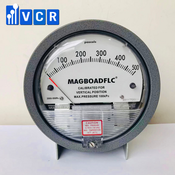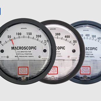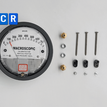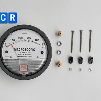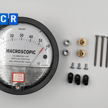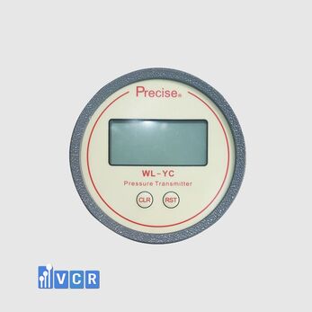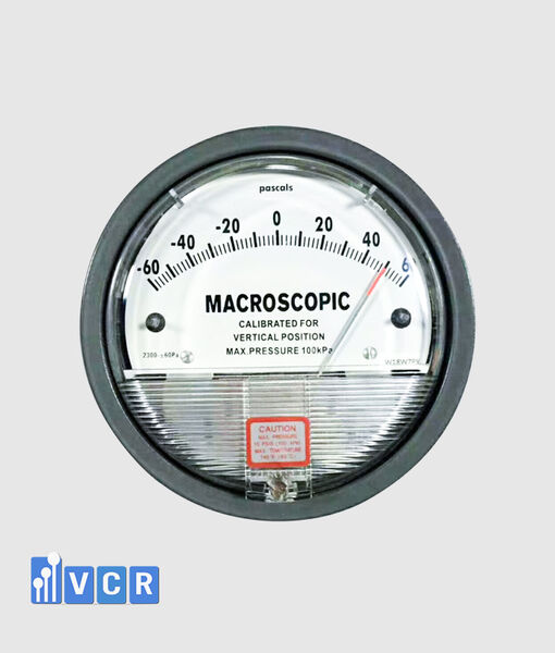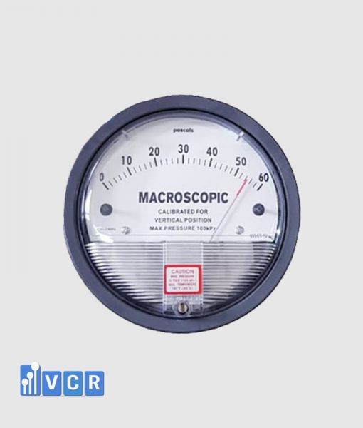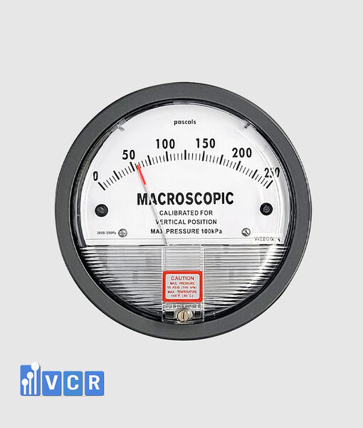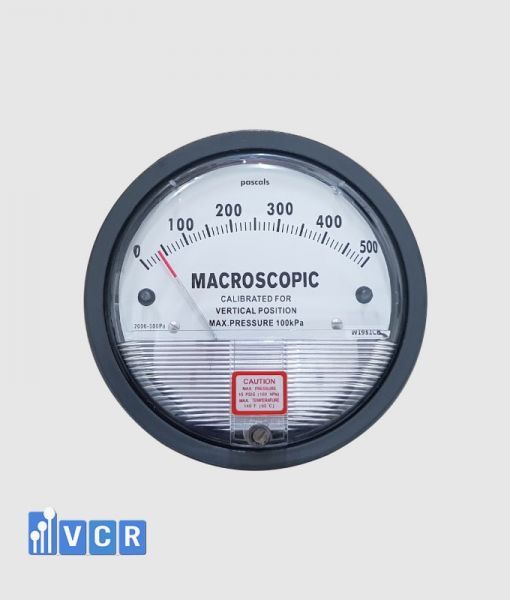

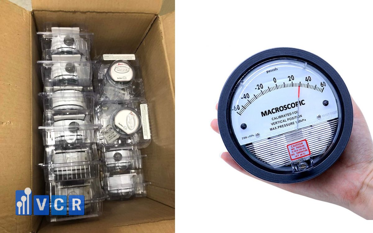
A HEPA filter clogging gauge monitors the pressure difference across the filter, helping operators identify dust loading, airflow restriction and the appropriate time for inspection, maintenance or filter replacement.
- What is a HEPA filter clogging gauge?
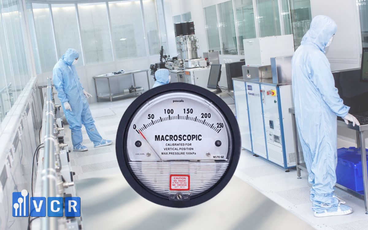
- How does a HEPA filter clogging gauge work?
- Types of HEPA filter clogging monitoring devices
- Why is an alarm threshold necessary?
- There is no universal HEPA filter clogging pressure
- How to configure the HEPA filter clogging alarm threshold
- Example of a three-level monitoring strategy
- How to select the correct pressure range
- Installation guidelines
- Alarm testing and commissioning
- Common monitoring problems
- Can a differential pressure gauge detect a damaged HEPA filter?
- Frequently asked questions
- Conclusion
What is a HEPA filter clogging gauge?
A HEPA filter clogging gauge is a differential pressure measuring device installed to monitor the pressure difference between the upstream and downstream sides of a HEPA filter.
It may also be referred to as a HEPA differential pressure gauge, filter pressure drop gauge, filter blockage indicator, filter loading gauge or filter differential pressure monitor.
When air passes through a HEPA filter, the filter media creates resistance to airflow. As airborne particles accumulate on the media, this resistance normally increases. The gauge detects the resulting pressure difference and displays it in units such as pascals, millimetres of water column or inches of water column.
The gauge does not directly measure the quantity of dust inside the filter. It also does not verify filtration efficiency or filter integrity. Instead, it uses pressure drop as an operational indicator of filter loading.
For this reason, differential pressure monitoring does not replace HEPA leak testing, airborne particle measurement or filter integrity testing.
How does a HEPA filter clogging gauge work?
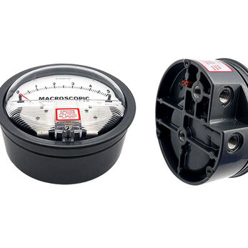
The gauge normally has two pressure ports:
-
The High, Positive or “+” port is connected to the upstream side of the HEPA filter.
-
The Low, Negative or “−” port is connected to the downstream side of the filter.
The measured value is calculated as:
Filter differential pressure = Upstream pressure − Downstream pressure
When the fan is running, the upstream pressure is usually higher than the downstream pressure. The gauge therefore displays a positive differential pressure.
As dust accumulates, the resistance of the filter media increases. At a similar airflow rate, the differential pressure across the filter gradually rises.
For example, a new HEPA filter may have an initial pressure drop of value A at the design airflow. After a period of operation, the pressure drop may increase to value B. If the fan speed, airflow and damper positions remain generally unchanged, the increase from A to B is an indication of filter loading.
However, pressure drop must always be interpreted in relation to airflow. If fan speed decreases, the differential pressure may also decrease even when the filter is dirty. If the airflow increases, pressure drop may rise even when the filter has not reached the replacement condition.
Types of HEPA filter clogging monitoring devices
Mechanical differential pressure gauge
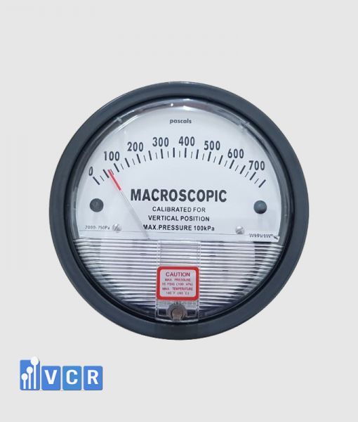
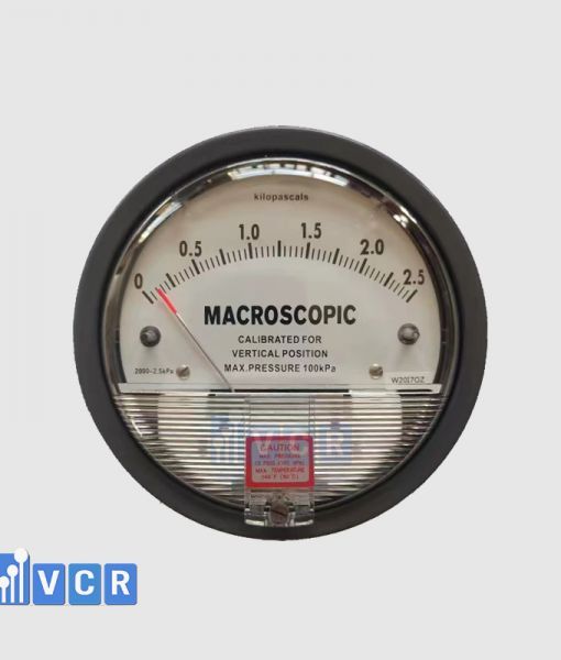
A mechanical needle-type gauge is widely used on AHUs, HEPA boxes, pass boxes, air showers, fan filter units and other cleanroom equipment.
It provides a direct local indication and normally does not require an external power supply. Its main advantages are simple construction, straightforward operation and relatively low cost.
Most mechanical gauges only provide a visual indication. Certain models may include adjustable contacts or alarm switches.
Electronic differential pressure gauge
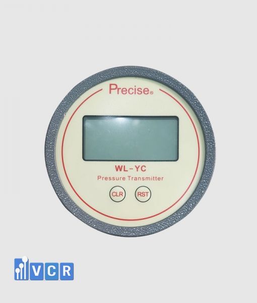
An electronic differential pressure gauge uses a pressure sensor and digital display. Depending on the model, it may provide relay outputs, 4–20 mA, 0–10 V, RS485 or Modbus communication.
Electronic instruments are suitable when the pressure value must be transmitted to a PLC, HMI, BMS or environmental monitoring system.
They may support configurable warning limits, high alarms, delay times, hysteresis and event recording.
Differential pressure switch
A differential pressure switch changes its electrical contact state when the pressure difference exceeds a configured value.
It may not provide continuous pressure indication. It is often used to activate a warning light, buzzer or control signal when a filter reaches a predefined pressure drop.
For systems requiring both local indication and remote alarming, a visual gauge may be combined with a pressure switch or differential pressure transmitter.
Why is an alarm threshold necessary?
Installing a gauge without establishing operating limits gives the operator a value but does not clearly define whether that value is normal or unacceptable.
A properly configured alarm threshold can help:
-
Detect increasing filter loading.
-
Provide early notice before airflow becomes inadequate.
-
Support preventive maintenance planning.
-
Reduce the risk of unstable room pressure.
-
Prevent the fan from operating at an unsuitable point.
-
Maintain airflow and cleanroom performance.
-
Create trend data for maintenance and qualification.
-
Reduce unplanned equipment shutdowns.
In pharmaceutical, electronics, semiconductor, medical device and food cleanrooms, filter differential pressure monitoring supports stable HVAC operation and contamination control.
There is no universal HEPA filter clogging pressure
A single pressure limit should not be applied to all HEPA filters.
The correct alarm threshold depends on:
-
HEPA filter model and construction.
-
Filter face dimensions.
-
Filter media area and pleat depth.
-
Rated airflow.
-
Actual operating airflow.
-
Initial resistance specified by the manufacturer.
-
Recommended final resistance.
-
Fan performance and available static pressure.
-
Ductwork and housing configuration.
-
Required room pressure and air velocity.
-
Cleanroom operating criteria.
-
Site maintenance and quality procedures.
The alarm limit should therefore be based on the filter manufacturer’s data, system design information and actual commissioning results.
A setpoint used on another project should not be copied without confirming that the filter type, airflow and system characteristics are comparable.
How to configure the HEPA filter clogging alarm threshold
Step 1: Establish the clean-filter baseline
After installing a new HEPA filter, operate the system at its approved design airflow. Allow fan speed, dampers and airflow conditions to stabilise.
Record the actual pressure drop across the clean filter. This becomes the clean-filter baseline for the installed system.
Catalogue data should not be used as the only reference because actual pressure drop may also be affected by airflow, filter housing, protective screens, installation arrangement and measurement point locations.
The baseline should be documented together with the airflow or fan operating condition at the time of measurement.
Step 2: Determine the final operating limit
The final differential pressure limit should consider the filter manufacturer’s recommended final resistance and the operational capability of the system.
In some installations, the system may fail to maintain the required airflow, air velocity or room pressure before the filter reaches the manufacturer’s nominal final resistance.
In such cases, the operational limit of the complete system may become the controlling criterion.
The replacement limit should not be based only on filter age or visual appearance.
Step 3: Set an early-warning threshold
An early-warning alarm allows maintenance personnel to review the trend, verify system conditions and prepare a replacement filter before performance becomes unacceptable.
One possible method is to calculate the warning point as a proportion of the allowable increase between the clean-filter baseline and the final limit.
For example:
Early warning = Clean pressure drop + 70% × (Final pressure drop − Clean pressure drop)
This equation is an example rather than a universal requirement. The percentage should be selected according to system criticality, maintenance response time and risk assessment.
Step 4: Set a high alarm or action limit
A high alarm may be positioned closer to the final operating limit, for example at approximately 85–90% of the allowable pressure-drop increase.
When the high alarm occurs, the operator should verify:
-
Actual airflow.
-
Fan speed.
-
Damper positions.
-
Pressure tubing condition.
-
Accuracy of the differential pressure instrument.
-
Condition and installation of the HEPA filter.
The action limit should be linked to a documented procedure. Depending on the application, the procedure may require inspection, filter replacement planning or equipment shutdown when required performance can no longer be maintained.
Step 5: Configure an alarm delay
Differential pressure may temporarily fluctuate during fan start-up, door operation, damper adjustment or variable-speed fan control.
If an alarm activates immediately, short transients can create nuisance alarms.
Electronic gauges, PLCs and BMS systems should therefore use an appropriate alarm delay. The alarm should be confirmed only when the differential pressure remains beyond the limit for the configured duration.
The delay should remove short disturbances without delaying the response to a genuine fault.
Step 6: Apply hysteresis or a reset differential
Without hysteresis, an alarm can repeatedly switch on and off when the measured value fluctuates close to the setpoint.
A reset differential allows the alarm to clear only after the pressure drops below a lower reset value.
This provides a more stable alarm response and prevents repeated relay operation.
Example of a three-level monitoring strategy
Normal operating range
Differential pressure remains within the approved operating range. The system continues to operate and values are recorded according to the monitoring schedule.
Early warning
The pressure drop reaches a level requiring closer observation. Maintenance personnel review the trend, verify airflow and prepare a maintenance plan.
High alarm or action condition
The pressure drop approaches the final limit or the system can no longer maintain the required airflow, room pressure or air velocity.
The operator follows the approved SOP, evaluates the system and replaces the filter when required.
A multi-level strategy is generally more useful than relying on a single filter-clogged alarm.
How to select the correct pressure range
The measuring range must be higher than the maximum expected differential pressure, but it should not be unnecessarily wide.
If the range is too narrow, the pointer or sensor may exceed its full scale when the filter becomes loaded or when airflow temporarily increases.
If the range is too wide, small but important pressure changes may be difficult to observe.
Selection should consider:
-
Initial pressure drop at design airflow.
-
Recommended final pressure drop.
-
Possible fan-speed or airflow increases.
-
Required display resolution.
-
Instrument accuracy.
-
Alarm setpoints.
-
Measurement unit used at the facility.
Common units include Pa, mmH₂O and in.w.c. Facilities should preferably use consistent units across gauges, drawings, SOPs and control systems to minimise conversion and setpoint errors.
Installation guidelines
The upstream pressure tapping point must be connected to the High port. The downstream tapping point must be connected to the Low port.
Pressure tubing should:
-
Be airtight.
-
Remain free from kinks and compression.
-
Be protected from blockage.
-
Avoid locations where condensation can accumulate.
-
Be clearly identified as High and Low.
-
Have a practical and controlled length.
-
Be connected to representative pressure points.
-
Avoid areas of excessive turbulence where possible.
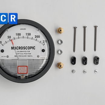
Mechanical gauges should be installed in the orientation specified by the manufacturer. Their zero position should be checked when the fan is stopped and both pressure ports are at equal pressure.
For electronic instruments, the installer should verify the power supply, display value, analogue output, relay operation, communication signal and connection to the PLC, HMI or BMS.
Alarm testing and commissioning
Commissioning should cover more than visual observation of the displayed value. The complete signal chain should be tested from the pressure ports to the gauge, PLC, HMI, buzzer, warning lamp and data-recording system.
A pressure calibrator or differential pressure source may be used to simulate:
-
A value below the warning setpoint.
-
A value at the warning setpoint.
-
A value above the warning setpoint.
-
A value at the high alarm.
-
A return to the normal range.
The test should confirm:
-
Display accuracy.
-
Alarm activation point.
-
Relay status.
-
Alarm message.
-
Alarm delay.
-
Hysteresis and reset behaviour.
-
Data transmission.
-
Alarm acknowledgement where applicable.
Blocking the HEPA filter to create a real pressure increase is generally not the preferred test method. It can overload the fan, damage the filter or disturb the airflow system.
Common monitoring problems
No pressure reading when the fan is operating
Possible causes include reversed tubing, disconnected tubing, leakage, blocked pressure lines or incorrectly positioned pressure tapping points.
Negative differential pressure
The High and Low connections may have been reversed. The tubing should be checked before assuming that the instrument is defective.
Sudden pressure increase
A rapid increase may be caused by filter loading, a closed damper, increased fan speed, airflow restriction or a blocked pressure tapping point.
Unexpectedly low pressure drop
A low value does not always indicate a clean filter. Possible causes include reduced fan speed, slipping belts, duct leakage, filter bypass, poor sealing or incorrect airflow.
Frequent nuisance alarms
The alarm threshold may be too close to the normal operating range, the alarm delay may be too short, or the pressure signal may be unstable.
Can a differential pressure gauge detect a damaged HEPA filter?
A differential pressure gauge cannot confirm HEPA filter damage by itself.
A torn filter or an improperly sealed filter may produce a lower pressure drop, but similar behaviour can result from reduced airflow or duct leakage.
Filter integrity must be confirmed by an appropriate aerosol leak test and measurement method. Differential pressure should be treated as an operational warning signal that triggers further investigation.
Frequently asked questions
At what differential pressure should a HEPA filter be replaced?
There is no single replacement value for all HEPA filters. The decision should be based on the manufacturer’s final resistance recommendation, actual airflow performance and the system’s ability to maintain the required air velocity or room pressure.
Can the alarm be set at twice the initial pressure drop?
Some facilities use this as an operating rule, but it should not be applied automatically. The filter specification, fan capability and system operating limits must first be reviewed.
Can a mechanical pressure gauge generate an alarm?
A standard mechanical gauge normally provides local indication only. Remote alarming requires a model with electrical contacts, a pressure switch or an electronic differential pressure transmitter.
Can increasing fan speed activate a clogging alarm?
Yes. Pressure drop across a filter increases with airflow. Filter condition should therefore be compared under similar operating conditions or evaluated using an airflow-compensated control strategy.
Does a HEPA differential pressure gauge require calibration?
The instrument should be inspected and calibrated according to the facility’s quality system, risk assessment and maintenance programme. Calibration and functional testing are especially important for GMP systems and alarms connected to control or interlock functions.
Conclusion
A HEPA filter clogging gauge works by measuring the differential pressure between the upstream and downstream sides of the filter.
For the alarm to provide meaningful information, the system owner must establish a clean-filter baseline at the approved airflow, define a final operational limit and configure suitable warning, high-alarm and delay settings.
A universal pressure limit should not be used for every HEPA filter. Setpoints should be based on the manufacturer’s data, system design, commissioning results, operating trends and risk assessment.
VCR Cleanroom Equipment supplies mechanical and electronic differential pressure gauges and monitoring solutions for AHUs, HEPA boxes, pass boxes, air showers, FFUs, laminar airflow units and cleanroom HVAC systems. Selecting the correct range, output signal and alarm strategy improves operating stability, maintenance planning and commissioning effectiveness.