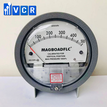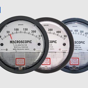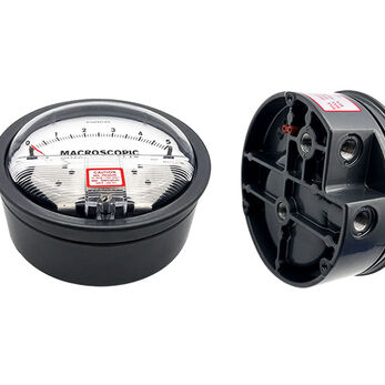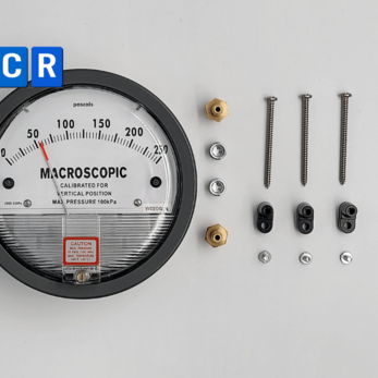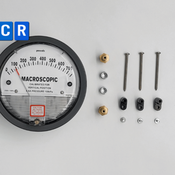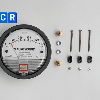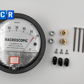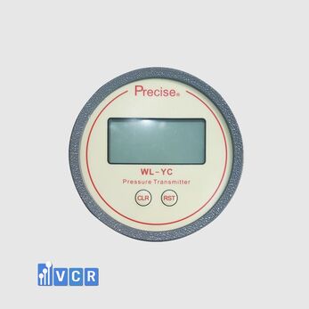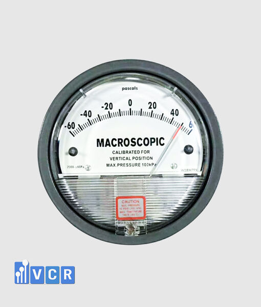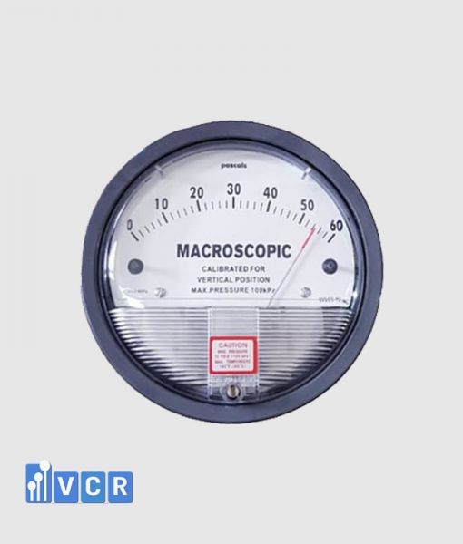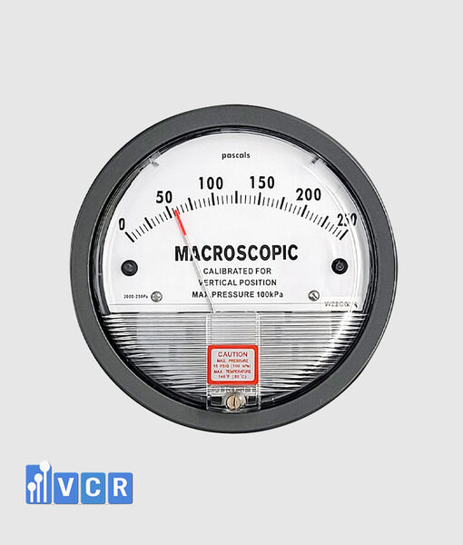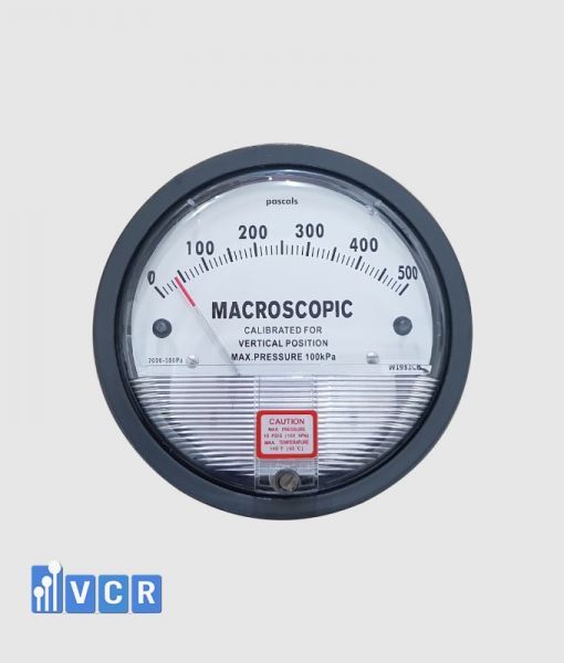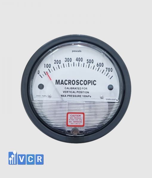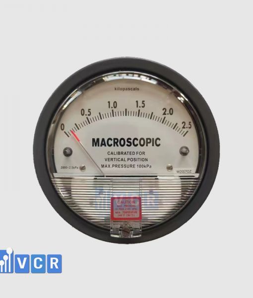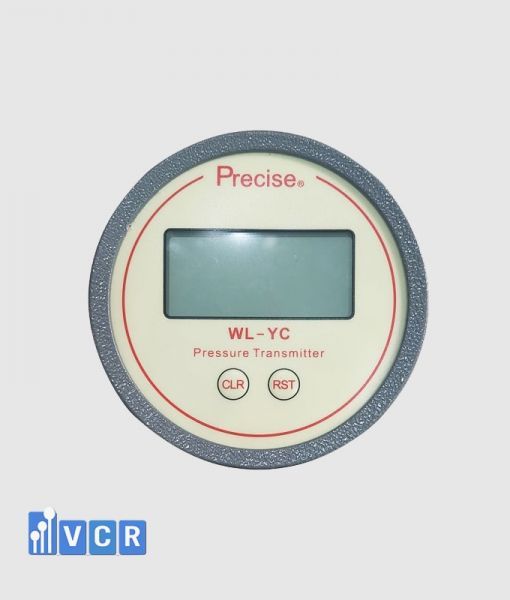

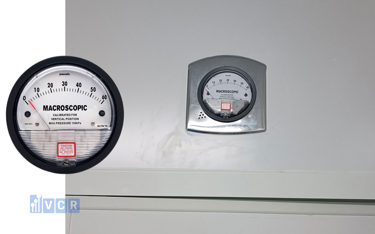
A differential pressure gauge helps control airflow direction between an ISO Class 8 cleanroom and adjacent areas. It should be selected according to its range, accuracy, output signal, alarms, installation location and calibration requirements.
- What is an ISO Class 8 cleanroom?
- Why is differential pressure important?
- Does ISO 14644 require 10 Pa for ISO Class 8?
- Is ISO Class 8 equivalent to Grade D?
- Does ISO Class 8 require HEPA filtration?
- Define the measurement purpose
- Select the correct measuring range
- Accuracy and zero stability
- Mechanical gauge or electronic transmitter?
- Output signals and central-system integration
- Establishing ISO Class 8 pressure alarms
- Suitability for the ISO Class 8 environment
- Pressure-tap location and tubing
- Calibration requirements
- Complete 4–20 mA loop verification
- Acceptance testing in cleanroom occupancy states
- Required technical and acceptance documents
- Common mistakes
- FAQ: ISO Class 8 differential pressure gauges
- ISO Class 8 differential pressure solutions from VCR Cleanroom Equipment
ISO Class 8 cleanrooms are used for processes that require airborne-particle control but do not require the same cleanliness level as ISO Class 5, ISO Class 6 or ISO Class 7.
The room may serve as a main production area, material-preparation room, packaging or assembly area, airlock, changing room or background environment for a higher-class clean zone.
Maintaining the controlled condition requires the HVAC system to provide sufficient filtered airflow, establish the intended airflow direction and maintain an appropriate pressure relationship with corridors, unclassified areas or adjacent cleanrooms.
A differential pressure gauge helps operators determine whether the designed airflow direction remains effective. It may also reveal an open door, reduced supply airflow, increased filter resistance, fan failure or another HVAC abnormality.
ISO 14644 does not prescribe one gauge model, measuring range or pressure value for every ISO Class 8 room. Instrument requirements should be based on the intended use, adjacent environment, airflow direction and monitoring plan.
What is an ISO Class 8 cleanroom?
ISO Class 8 is an air-cleanliness classification defined by ISO 14644-1. The standard classifies cleanrooms and clean zones according to airborne-particle concentration at specified particle sizes. Differential pressure, air-change rate and filter type do not directly determine the ISO classification.
A room cannot therefore be confirmed as ISO Class 8 merely because it operates under positive pressure or uses HEPA filtration. Airborne-particle classification must be performed using an appropriate particle-counting method.
Differential pressure is a supporting environmental parameter. It does not replace particle-counting equipment or a cleanroom-classification report.
An ISO Class 8 cleanroom may be configured as:
-
An independent production room.
-
A background room for ISO Class 7 or a higher-class clean zone.
-
A material- or component-preparation area.
-
A packaging or assembly room.
-
A changing room or airlock.
-
A room containing a Clean Booth or Mini-environment.
-
A space served by an AHU, HEPA Boxes or FFUs.
-
A negative-pressure containment room.
Each arrangement may require a different pressure cascade, number of monitoring points and monitoring method.
Why is differential pressure important?
Differential pressure establishes the intended direction of air movement between spaces.
Under a conventional positive-pressure arrangement, the ISO Class 8 room is maintained above the pressure of a corridor or unclassified area. Air therefore tends to move outward through leakage paths, reducing the entry of particles, fibres, dust or other contamination.
ISO Class 8 may also provide the background for an ISO Class 7 room, Clean Booth, LAF unit or localized higher-class zone. Stable background pressure can support the performance of these cleaner areas.
Some processes require negative pressure to contain powders, chemicals, biological agents or other hazardous contamination. In these cases, the gauge confirms the inward airflow direction required for containment.
Positive pressure is therefore not universally correct. The pressure arrangement should meet the product-protection, personnel-protection and environmental-containment objectives of the process.
Does ISO 14644 require 10 Pa for ISO Class 8?
ISO 14644 does not require every ISO Class 8 cleanroom to maintain a 10 Pa pressure difference.
ISO 14644-1 addresses classification by airborne-particle concentration. ISO 14644-2 specifies minimum requirements for a monitoring plan based on parameters that measure or affect airborne-particle concentration.
Ten pascals is referenced in some industry-specific standards and guidance documents. It should not automatically be applied to every ISO Class 8 project.
The required pressure should be based on:
-
Cleanliness and function of adjacent spaces.
-
Intended airflow direction.
-
Leakage through panels, ceilings and doors.
-
Door gaps and other openings.
-
Supply, return and exhaust airflow.
-
Door-opening frequency.
-
Personnel and equipment loads.
-
Product-protection requirements.
-
Containment requirements.
-
Cross-contamination risk.
-
HVAC balancing and performance-test results.
A facility may use 5 Pa, 10 Pa, 15 Pa, 20 Pa or another justified value where testing confirms that the intended airflow direction and segregation are maintained.
Two adjacent ISO Class 8 rooms may also use a pressure difference to control personnel flow, material movement or cross-contamination between processes.
Is ISO Class 8 equivalent to Grade D?
ISO Class 8 and pharmaceutical Grade D should not be treated as fully equivalent concepts.
ISO Class 8 is an airborne-particle classification under ISO 14644-1. Grade D is a pharmaceutical cleanroom grade associated with specified manufacturing activities and additional requirements for occupancy state, microbiological control, operation and GMP monitoring.
An ISO Class 8 room does not automatically qualify as Grade D. A Grade D room may need to meet an applicable particle condition while also complying with additional GMP requirements.
The project should identify whether only ISO 14644 applies or whether EU GMP, WHO GMP, PIC/S GMP, medical-device requirements or customer-specific standards also apply.
Does ISO Class 8 require HEPA filtration?
ISO 14644-1 defines the class according to airborne-particle concentration and does not directly prescribe one filter model or filter grade for every ISO Class 8 room.
Many ISO Class 8 installations use HEPA filtration at the AHU, HEPA Box or terminal supply point. The actual filtration arrangement should reflect the contamination load, outdoor-air quantity, recirculation strategy, manufacturing application and required classification result.
A room differential pressure gauge does not indicate HEPA-filter condition. Where filter resistance must be monitored, a separate filter differential-pressure point with a suitable range should be provided.
Define the measurement purpose
Typical ISO Class 8 pressure-monitoring points include:
-
ISO Class 8 versus an unclassified corridor.
-
ISO Class 8 versus ISO Class 7.
-
Cleanroom versus an airlock.
-
Cleanroom versus a changing room.
-
Production room versus a support space.
-
Negative-pressure room versus an adjacent area.
-
Clean Booth versus the ISO Class 8 background.
-
Across a HEPA filter in a HEPA Box.
-
Across AHU pre-filters or intermediate filters.
-
On a Pass Box, Air Shower or Dispensing Booth.
Room differential pressure and filter differential pressure serve different purposes.
Room pressure indicates the direction of airflow between spaces. Filter pressure indicates changes in filter resistance during operation.
These duties normally require different ranges, alarm settings and evaluation criteria.
Select the correct measuring range
The range should match the design operating pressure.
An excessively wide span makes small changes difficult to observe. A range that is too narrow may overrange during door opening, HVAC start-up or temporary imbalance.
For pressure between an ISO Class 8 room and an adjacent area, 0–25 Pa or 0–50 Pa may be considered where these ranges match the design. They are engineering examples rather than mandatory ISO 14644 values.
A bidirectional span such as ±25 Pa or ±50 Pa may be suitable where:
-
Pressure reversal is possible.
-
Both positive and negative pressure must be monitored.
-
The room has multiple operating modes.
-
Containment is required.
-
Reference pressure may vary.
The final range should consider:
-
Target operating value.
-
Normal operating range.
-
Alert level.
-
Action limit.
-
Door-opening transients.
-
Maximum credible pressure.
-
Sensor overpressure capability.
The normal operating value should fall within a clearly readable part of the span while leaving sufficient capacity for abnormal conditions.
Accuracy and zero stability
ISO 14644 does not prescribe one accuracy class for every ISO Class 8 differential pressure gauge.
Required accuracy should reflect the measurement purpose and the separation between the normal value, alert level and action limit.
Where a room operates at 15 Pa and has a 10 Pa action limit, the combined error of the sensor, signal transmission, input module and display system should be small enough to distinguish reliably between the two conditions.
Instrument assessment should include:
-
Accuracy within the working region.
-
Repeatability.
-
Zero drift.
-
Long-term stability.
-
Temperature and humidity effects.
-
Overpressure resistance.
-
Display resolution.
-
Calibration uncertainty.
-
Zero-adjustment method.
Zero stability is particularly important for low-range sensors. A shift of only a few pascals can represent a significant proportion of the room-pressure value.
A resolution of 0.1 Pa or 1 Pa may be appropriate depending on the measuring span. Additional display digits do not necessarily indicate better measurement accuracy.
Mechanical gauge or electronic transmitter?
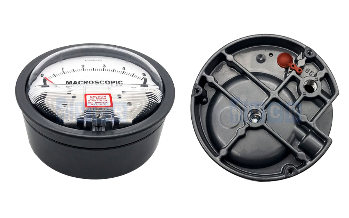
A mechanical differential pressure gauge may be suitable for local indication or periodic manual recording.
It is simple, requires no electrical supply and provides an immediate visual indication.
A basic mechanical gauge normally cannot:
-
Record data automatically.
-
Generate remote alarms.
-
Communicate with a BMS or EMS.
-
Store event time stamps.
-
Display pressure trends.
-
Detect signal failure.
An electronic transmitter or digital gauge is generally more suitable where the pressure relationship directly affects ISO Class 8 control, supports a higher-class clean zone or requires automatic alarms.
ISO 14644-2 requires a monitoring plan based on parameters that measure or affect airborne-particle concentration. Monitoring frequency should therefore be established through the monitoring plan and risk assessment rather than by the ISO Class 8 designation alone.
Output signals and central-system integration
Electronic instruments may provide:
-
4–20 mA.
-
0–10 V.
-
Modbus RTU.
-
Modbus TCP.
-
BACnet.
-
Alarm relays.
-
Ethernet communication where available.
A 4–20 mA output is widely used because it is suitable for practical transmission distances and integrates readily with a PLC, BMS, EMS or SCADA system.
Where the central-system value is used to determine room status, the complete measurement loop should be verified from the applied pressure to the displayed and stored value.
The system should also identify:
-
Sensor power loss.
-
Open signal wiring.
-
Out-of-range signals.
-
Frozen readings.
-
Communication failure.
-
Sensor or zero-adjustment faults.
An instrument failure should not result in a false normal indication.
Establishing ISO Class 8 pressure alarms
Alarm limits should not be copied from another room or automatically set at 10 Pa.
A practical alarm strategy normally includes:
-
Target operating value.
-
Normal operating range.
-
Alert level.
-
Action limit.
-
Alarm delay.
-
Reset hysteresis.
-
Defined operator response.
Where a room normally operates at 15 Pa and has a 10 Pa action limit, the alert level may need to be above 10 Pa so deterioration is identified before control is lost.
An alarm delay can reduce nuisance events caused by brief door openings. An excessive delay may conceal a genuine loss of segregation.
Alarm settings should be established after HVAC balancing and review of operational data. The alarm should be challenged by creating an unacceptable pressure condition or simulating the corresponding input signal.
Suitability for the ISO Class 8 environment
A cleanroom-mounted instrument should minimize particle accumulation and allow effective cleaning.
The front surface should preferably be flush or nearly flush with the wall panel. Gaps around the instrument should be sealed using materials compatible with the cleanroom construction.
The housing, display and seals should withstand the cleaning agents, disinfectants or process chemicals used in the area.
For electronics and semiconductor applications, additional considerations may include:
-
Particle-shedding materials.
-
Chemical emissions.
-
Electrostatic-discharge requirements.
-
Airborne molecular contamination.
-
Corrosion resistance.
-
Process-chemical compatibility.
-
Ionic or metallic contamination risk.
ISO 14644-4:2022 addresses the cleanroom lifecycle from requirements through design, construction and start-up. Instrument location, functionality and acceptance criteria should therefore be defined during the URS or design stage.
Pressure-tap location and tubing
The pressure tap should measure representative room static pressure.
It should not be installed:
-
Directly in a supply-air jet.
-
In a high-velocity airflow region.
-
Too close to a return-air grille.
-
Directly at a door gap.
-
Near a fan or pressure disturbance.
-
Where it may be obstructed.
-
Where liquid may accumulate.
The high- and low-pressure ports must be connected correctly. Reversed connections will produce an incorrect sign or airflow direction.
Tubing should be leak-tight and protected against kinking, crushing and liquid accumulation. Both lines should be clearly identified to prevent incorrect reconnection during installation or maintenance.
Where a reference port is located in a ceiling void or wall cavity, the designer should verify that this space represents the intended reference pressure.
Calibration requirements
The instrument should be calibrated before use and at approved intervals.
Calibration should not be limited to zero. Test points should cover:
-
The normal operating region.
-
Alert level.
-
Action limit.
-
The upper part of the working span where relevant.
The reference instrument should have suitable accuracy and metrological traceability.
The calibration certificate should state individual test results, errors, acceptance criteria and calibration uncertainty where applicable.
Calibration frequency should reflect measurement criticality, manufacturer recommendations, environmental conditions and historical drift.
Where an instrument is found out of tolerance, the facility should assess the effect on previous pressure data and on the ISO Class 8 condition during the affected period.
Complete 4–20 mA loop verification
Where the official reading is taken from a BMS or EMS, the transmitter calibration certificate alone does not verify the complete measuring system.
Loop testing should confirm:
-
Reference pressure.
-
Local transmitter display.
-
Output current.
-
PLC analogue-input value.
-
HMI, BMS or EMS indication.
-
Relay status.
-
Alarm operation.
-
Historical data record.
Error can originate in the sensor, signal converter, wiring, analogue-input module, software or scaling configuration.
Acceptance testing in cleanroom occupancy states
ISO 14644-3:2019 provides test methods for cleanrooms and clean zones using unidirectional or non-unidirectional airflow in as-built, at-rest and operational states.
Differential pressure acceptance testing should consider:
-
Stable HVAC operation.
-
Door opening and closing.
-
Pressure recovery time.
-
Personnel and equipment effects.
-
Airlock operation.
-
Fan failure or reduced airflow.
-
Sensor-signal loss.
-
Power failure and restoration.
-
Alarm operation.
-
Agreement between local and central values.
The required occupancy state and acceptance criteria should be specified in the URS, design documents or acceptance plan before testing.
Required technical and acceptance documents
The ISO Class 8 differential pressure documentation package should include:
-
User Requirement Specification.
-
Technical datasheet.
-
Model, serial number and measuring range.
-
Installation-location drawing.
-
High- and low-pressure connection diagram.
-
Electrical wiring diagram.
-
Calibration certificate.
-
On-site test results.
-
Signal-loop test record.
-
Alarm-challenge record.
-
Operating and maintenance instructions.
-
Inspection and calibration procedure.
-
Maintenance history.
-
Setpoint-change records.
-
Impact assessment following an out-of-tolerance result.
ISO 14644-5:2025 requires an operations control programme covering personnel, material entry and exit, cleaning, maintenance and monitoring. The instrument should therefore remain controlled throughout the cleanroom lifecycle rather than only during initial handover.
Common mistakes
Common errors include:
-
Assuming ISO Class 8 always requires 10 Pa.
-
Selecting an excessively wide range.
-
Using one range for room and HEPA-filter pressure.
-
Reviewing only percentage-of-full-scale accuracy.
-
Ignoring zero drift.
-
Positioning the pressure tap beside a supply diffuser.
-
Reversing the high- and low-pressure ports.
-
Failing to check tubing leakage.
-
Calibrating the transmitter without checking the loop.
-
Failing to challenge alarms under operating conditions.
-
Failing to determine recovery after door opening.
-
Assuming pressure monitoring replaces particle classification.
FAQ: ISO Class 8 differential pressure gauges
Must an ISO Class 8 room maintain 10 Pa?
No. ISO 14644 does not define one universal pressure difference for every ISO Class 8 room. The value should be based on airflow direction, background cleanliness, HVAC configuration, manufacturing application and risk assessment.
Does ISO Class 8 require continuous pressure monitoring?
The ISO class alone does not determine monitoring frequency. The monitoring plan should define the frequency according to the effect of differential pressure on cleanroom performance. Critical points or background rooms supporting a higher-class clean zone are often suitable for continuous monitoring.
Can a mechanical gauge be used?
Yes, for local observation or periodic manual recording. A point directly affecting the ISO Class 8 condition should normally use an electronic transmitter with alarms and signal output.
Does a differential pressure gauge prove ISO Class 8 compliance?
No. ISO Class 8 is determined by airborne-particle concentration testing under ISO 14644-1. Differential pressure is a supporting parameter used to maintain the controlled condition.
Can a room-pressure gauge measure HEPA-filter pressure?
Only where its range, accuracy and overpressure capability are suitable. Filter pressure loss is generally higher than room-to-room differential pressure and normally requires a separate range.
ISO Class 8 differential pressure solutions from VCR Cleanroom Equipment
VCR Cleanroom Equipment supplies and supports the selection of differential pressure gauges, transmitters and monitoring solutions for ISO Class 8, ISO Class 7, ISO Class 6 and ISO Class 5 cleanrooms, Clean Booths, FFUs, LAF units, Pass Boxes, Air Showers, Dispensing Booths, HEPA Boxes and HVAC systems.
VCR can assist with defining the measurement purpose, range, accuracy, 4–20 mA output, Modbus communication, alarm functions, calibration requirements and acceptance documentation for each project.
Hotline: 090.123.9008
Email: [email protected]
Website: https://vietnamcleanroom.com