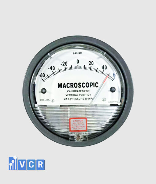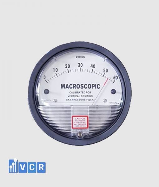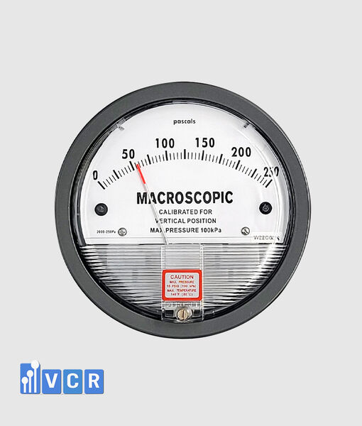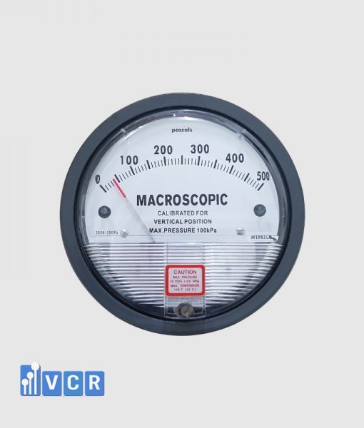

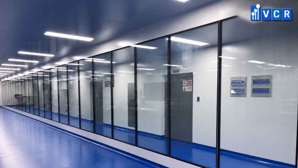
Installing a differential pressure gauge on tempered glass requires a suitable mounting solution that ensures glass safety, partition airtightness, and reliable pressure measurement. This technical case study examines three installation methods, mounting accessories, technical requirements, verification procedures, and recommendations for cleanroom contractors.
- Executive Summary
- Project Overview
- Technical Requirements
- Technical Challenges
- Solution Analysis: Three Installation Methods
- Equipment Configuration and Mounting Accessories
- Implementation Process
- Testing and Verification
- Results and Expected Outcomes
- Applicable Standards and Technical References
- Lessons Learned for Cleanroom Contractors
- FAQ – Frequently Asked Questions About Differential Pressure Gauge Installation on Tempered Glass
- Conclusion and Recommendations
Executive Summary
Installing a differential pressure gauge on a tempered glass partition presents a specific engineering challenge in cleanroom construction and renovation projects.
Unlike conventional sandwich panels, finished tempered glass cannot be drilled or cut to accommodate additional instrumentation. At the same time, differential pressure gauges must be securely installed, easily accessible, correctly connected to pressure measurement points, and positioned without compromising the integrity of the cleanroom partition.
This technical case study evaluates three installation approaches:
-
Mounting through a pre-fabricated opening in tempered glass.
-
Installing the gauge on a structural glass frame using a suitable mounting bracket.
-
Installing the gauge on an independent supporting structure without direct contact with the glass.
The analysis considers mechanical safety, installation feasibility, airtightness, measurement reliability, maintenance accessibility, and compatibility with cleanroom requirements.
The findings indicate that no single installation method is universally suitable. For new construction, a pre-designed glass opening may be considered. For existing tempered glass partitions, frame-mounted or independently supported configurations are generally more practical alternatives.
Case study classification: Technical Case Study – Engineering Application Analysis.
Data statement: This article presents an illustrative engineering scenario rather than a documented completed project. Any example specifications or calculations are identified accordingly. No actual project acceptance results or verified field measurements are claimed.
Project Overview
The scenario involves an industrial cleanroom facility where tempered glass partitions separate controlled production areas from adjacent corridors or technical spaces.
The facility requires local differential pressure indication to support monitoring of pressure relationships between two areas.
A mechanical differential pressure gauge is proposed for installation at a location where operators and maintenance personnel can conveniently observe its readings.
However, the existing tempered glass partition has already been manufactured and installed without an opening for the gauge.
The cleanroom contractor must therefore identify a mounting solution that avoids unsafe modification of the glass while maintaining the functionality of the pressure monitoring arrangement.
Project scenario information
| Parameter | Illustrative project information |
|---|---|
| Application | Industrial cleanroom |
| Measurement purpose | Room-to-room differential pressure monitoring |
| Partition material | Tempered glass with a supporting frame |
| Existing condition | Completed glass partition without a gauge opening |
| Instrument type | Mechanical differential pressure gauge |
| Example measurement range | 0–60 Pa |
| Installation alternatives | Through-glass, frame-mounted, independent support |
| Evaluation criteria | Safety, airtightness, measurement reliability, accessibility |
| Actual acceptance data | Not available |
The 0–60 Pa range is an illustrative instrument selection rather than a mandatory measurement range for cleanroom applications.
The appropriate gauge range must be determined from the intended operating pressure, allowable deviations, required accuracy, and project specifications.
Technical Requirements
A successful differential pressure gauge installation on tempered glass must satisfy several technical requirements simultaneously.
These include structural safety, instrument compatibility, pressure transmission integrity, cleanroom contamination control, and maintenance accessibility.
Tempered glass structural requirements
Tempered glass undergoes thermal treatment to create compressive stresses near its surfaces and tensile stresses within the glass.
This stress distribution improves its mechanical performance under appropriate conditions but also makes post-tempering cutting or drilling unsafe.
Any holes or cutouts must be designed and fabricated before the tempering process.
If a gauge is to be installed through the glass, the glass manufacturer or a qualified glazing specialist must evaluate the opening dimensions, edge distances, glass thickness, and mounting arrangement.
A mounting hole dimension specified for a metal panel cannot automatically be used as an approved opening for tempered glass.
Differential pressure gauge requirements
The selected gauge must provide a suitable measurement range, accuracy, readability, and environmental compatibility.
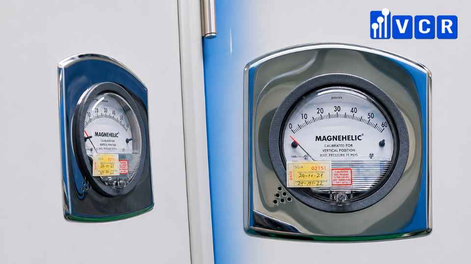
For mechanical gauges, installation orientation can affect zero adjustment and measurement performance.
Models calibrated for vertical installation should be mounted according to the manufacturer's instructions.
The gauge must also be positioned so that operators can read the display without unnecessary obstruction or unsafe access.
Pressure connection requirements
The pressure transmission system must provide sufficiently airtight connections between the pressure sampling points and the gauge.
Pressure tubing should not be excessively bent, crushed, obstructed, or exposed to mechanical damage.
High-pressure and low-pressure ports must be connected according to the measurement configuration.
Pressure sampling points must be selected to represent the intended room pressures while minimizing the effects of supply air jets and localized disturbances.
Cleanroom requirements
Mounting accessories and structural penetrations should not create unnecessary leakage paths, particle accumulation points, or surfaces that are difficult to clean.
Materials should be compatible with the facility's cleaning and disinfection procedures.
For pharmaceutical cleanrooms, installation arrangements should also be considered within the facility's contamination control strategy.
A mechanical gauge provides local indication but does not automatically satisfy requirements for continuous recording, alarms, or centralized monitoring.
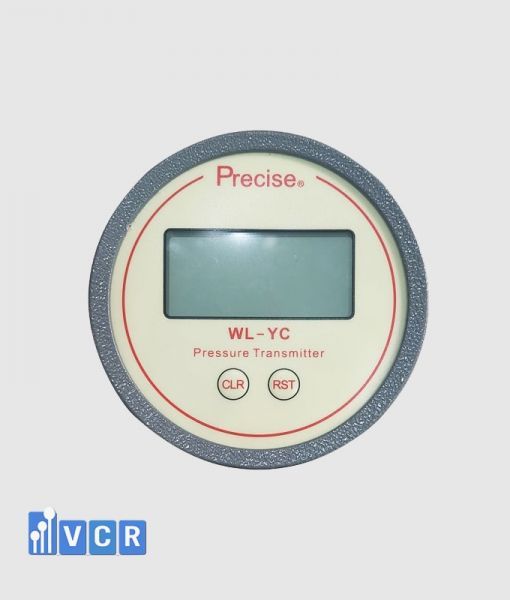
Where those functions are required, suitable electronic pressure transmitters and monitoring systems should be considered.
Technical Challenges
Installing differential pressure gauges on tempered glass partitions presents several challenges that differ from conventional wall or panel installations.
Challenge 1: Avoiding glass damage
The primary challenge is that an existing tempered glass panel cannot be drilled to accommodate a conventional gauge mounting opening.
Attempting to drill or cut finished tempered glass creates a significant risk of glass breakage.
Alternative mounting arrangements must therefore avoid direct modification of the glass unless the entire panel is replaced with a properly manufactured component.
Challenge 2: Maintaining mechanical stability
A differential pressure gauge generates mechanical loads through its own weight, mounting hardware, tubing connections, and maintenance activities.
Additional loads may occur when personnel inspect, clean, adjust, or replace the instrument.
A bracket clamped directly to glass without proper engineering evaluation may concentrate stresses and introduce structural risks.
The mounting system must transfer mechanical loads to an appropriate supporting structure.
Challenge 3: Limited installation space
Cleanroom glass partitions frequently incorporate aluminum or steel frames, sealing gaskets, door assemblies, and architectural components.
These elements can restrict available mounting locations.
The installation must also provide sufficient clearance for pressure tubing, connections, inspection, and maintenance.
Challenge 4: Preserving airtightness
Where pressure tubing penetrates a frame or an adjacent wall, the penetration must be properly sealed.
Uncontrolled air leakage can affect pressure relationships between adjacent cleanroom areas.
Even when the gauge is mounted independently, pressure tubing penetrations still require attention.
Challenge 5: Maintaining measurement reliability
Secure mechanical mounting alone does not guarantee accurate pressure measurement.
Incorrect port connections, leaking tubing, unsuitable pressure tap locations, and improper instrument orientation can all introduce measurement errors.
Therefore, the installation must be evaluated as a complete measurement system rather than as a mounting problem alone.
Solution Analysis: Three Installation Methods
Three principal installation arrangements are examined for different cleanroom construction conditions.
Solution A: Through-glass mounting using a pre-fabricated opening
This approach is most suitable for new construction or projects where the glass panel will be replaced.
The required opening is identified during the design stage and fabricated before the glass undergoes tempering.
The gauge is installed using a compatible mounting assembly, protective spacers, and an appropriate sealing arrangement.
The installation must avoid excessive concentrated loads on the glass.
Its principal advantage is the potential for a neat and integrated appearance.
However, this method requires close coordination between the gauge supplier, cleanroom contractor, mounting hardware designer, and glass manufacturer.
The glass manufacturer must confirm the feasibility of the opening, including its location and dimensions.
It is not appropriate to assume that a standard gauge panel cutout is automatically suitable for a tempered glass panel.
Solution B: Frame-mounted gauge using a mounting bracket
This solution attaches the gauge to an appropriate structural component of the glass partition frame rather than to the glass itself.
A compatible bracket or mounting plate supports the gauge, while pressure tubing connects it to the required measurement points.
The major advantage is that the existing glass panel can remain unchanged.
Installation and future gauge replacement may also be easier when the bracket is properly positioned.
However, not every section of a glass frame can support additional equipment.
Thin aluminum trims, decorative covers, and glazing retaining components must not be assumed to provide adequate structural support.
Before installation, contractors should verify the structural frame design, allowable loads, fixing locations, and the effect of any fasteners on partition integrity.
For renovation projects, this is often an appropriate option to evaluate first.
Solution C: Independent mounting support
An independent mounting arrangement supports the gauge using a separate structural element, such as an adjacent wall or a dedicated equipment support.
The gauge can be positioned close to the glass partition without transferring mechanical loads directly to the glass.
This approach offers considerable flexibility in installation location, maintenance accessibility, and pressure tubing routing.
It can be particularly useful where the existing glass frame does not provide a suitable structural fixing point.
However, additional mounting components, installation space, and tubing may be required.
The independent structure must still be designed and installed safely, with all pressure connections appropriately protected.
Comparison of installation methods
| Evaluation criterion | Pre-fabricated glass opening | Frame-mounted bracket | Independent support |
|---|---|---|---|
| Existing glass without an opening | Requires replacement or redesign | Potentially suitable | Potentially suitable |
| Glass drilling after tempering | Not permitted | Not required | Not required |
| Mechanical load on glass | Must be evaluated | Avoided if correctly designed | Avoided |
| Structural assessment | Glass and mounting assembly | Supporting frame | Independent structure |
| Appearance | Can be integrated | Depends on bracket design | Depends on location |
| Renovation flexibility | Limited | Relatively flexible | Highly flexible |
| Maintenance access | Depends on clearance | Can be convenient | Can be convenient |
| Cost considerations | Glass fabrication and mounting | Bracket and frame compatibility | Additional support and tubing |
Recommended approach for the illustrative scenario
For an existing tempered glass partition without a mounting opening, the frame-mounted bracket should be evaluated first.
If the supporting frame cannot safely accommodate the instrument, an independent mounting structure should be considered.
Direct drilling of finished tempered glass must not be used as a retrofit installation method.
These recommendations are preliminary engineering considerations and do not replace site-specific structural assessment.
Equipment Configuration and Mounting Accessories
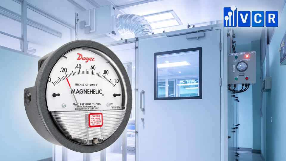
The proposed configuration includes a mechanical differential pressure gauge, mounting bracket, pressure tubing, suitable fittings, pressure sampling points, and sealing components.
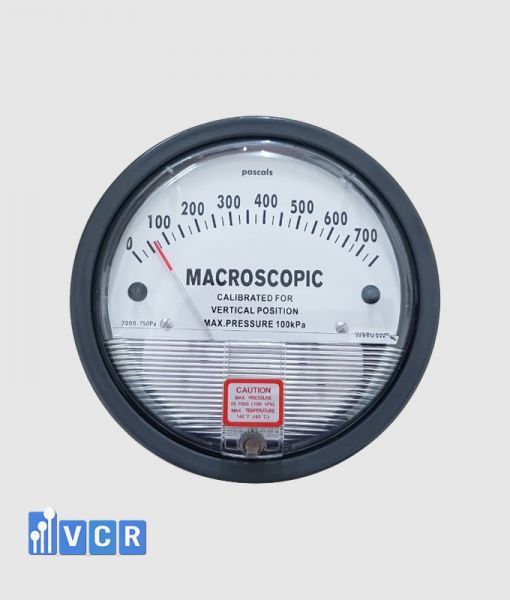
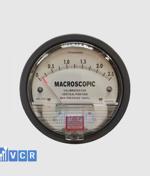
A Dwyer Magnehelic Series 2000 gauge or an instrument with comparable performance may be considered for illustration.
The final instrument must be selected according to the actual pressure range, accuracy requirements, environmental conditions, and project specifications.
Illustrative equipment configuration
| Component | Technical specification or consideration |
|---|---|
| Instrument | Mechanical differential pressure gauge |
| Reference series | Dwyer Magnehelic Series 2000 |
| Illustrative range | 0–60 Pa, subject to exact model selection |
| Mounting orientation | According to instrument specifications |
| Mounting arrangement | Frame-mounted or independent bracket |
| Reference pressure connection | 1/8-inch female NPT for standard Series 2000 |
| Pressure tubing | Compatible material and dimensions |
| Tube fittings | Suitable for tubing and gauge ports |
| Pressure sampling | Two representative pressure locations |
| Sealing components | Compatible with partition construction |
| Verification | Zero check, leakage inspection, reference comparison |
NPT stands for National Pipe Taper, a tapered pipe-thread specification commonly used in industrial instruments.
The table represents an illustrative configuration, not a confirmed packaged product kit.
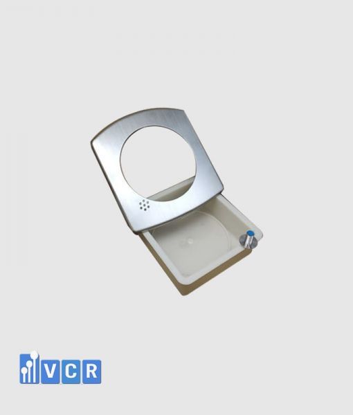
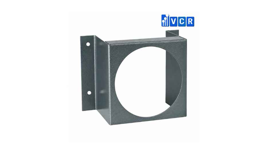
Mounting brackets
The bracket must be compatible with the gauge body, mounting dimensions, and fixing requirements.
For some Dwyer Magnehelic Series 2000 models, optional mounting accessories provide arrangements for surface mounting, pipe mounting, or flush mounting.
A-299 is an example of a mounting bracket accessory associated with the Magnehelic product family.
However, the suitability of a bracket for a particular glass frame must be evaluated separately.
Compatibility with the gauge does not automatically establish compatibility with the structural mounting surface.
Pressure tubing
Pressure tubing transfers pressure from the sampling points to the instrument.
Silicone, PVC, polyurethane, or other compatible materials may be used depending on manufacturer recommendations and environmental requirements.
Tubing should be routed to avoid kinks, obstructions, mechanical damage, and potential condensation accumulation.
For extended pressure lines, the system's response characteristics and maintenance requirements should also be considered.
Pressure fittings
Fittings must match the instrument port specifications and tubing dimensions.
Potential components include threaded adapters, barbed fittings, compression connections, and other manufacturer-approved connectors.
Unused pressure ports must be handled according to the gauge's measurement configuration and installation instructions.
An atmospheric reference port, where required, must not be sealed indiscriminately.
Mounting materials
Stainless steel, aluminum, or other suitably finished materials may be considered for brackets and mounting plates.
Selection should account for corrosion resistance, mechanical strength, cleanability, and compatibility with cleaning chemicals.
Stainless steel 304 may be appropriate for many installations, but material selection should be based on actual environmental conditions rather than a universal assumption.
Implementation Process
A systematic installation process helps ensure that both the mounting arrangement and pressure measurement system meet project requirements.
Site inspection
The contractor should inspect the existing glass partition, supporting frame, available mounting space, and pressure tubing routes.
The condition and construction of the glass assembly must be documented before selecting a mounting method.
Measurement requirements
The contractor must identify the two areas to be monitored, the expected pressure relationship, the gauge measurement range, and the required display location.
It is also necessary to establish whether local indication is sufficient or whether electronic recording and alarming are required.
Mounting design
A mounting drawing should indicate bracket dimensions, fixing points, gauge position, tubing connections, and maintenance clearances.
For a custom bracket, the design should be reviewed against the supporting structure and instrument requirements.
Accessory preparation
The gauge model, mounting hardware, fittings, tubing, and sealing materials should be checked before installation.
Any specially fabricated mounting components should be inspected against approved drawings.
Mechanical installation
The mounting assembly is installed at the approved position.
The gauge is secured according to the manufacturer's mounting instructions.
No drilling or cutting should be performed on an already tempered glass panel.
Pressure connection
High-pressure and low-pressure tubing connections are made according to the measurement arrangement.
The tubing should be supported where necessary and protected against kinking or accidental disconnection.
Completion inspection
After installation, the contractor should inspect mechanical stability, pressure line integrity, zero indication, display readability, and accessibility for maintenance.
Any partition penetrations should be sealed according to the approved cleanroom construction requirements.
Testing and Verification
The installation should be verified through a combination of mechanical inspection, pressure circuit checks, and instrument performance testing.
Mechanical inspection
Inspect the glass, supporting frame, mounting bracket, and instrument housing.
Confirm that the bracket is stable and that the installation has not introduced visible damage or unintended mechanical stress.
All tubing and accessories should be securely positioned.
Pressure line integrity
Pressure tubing and fittings should be checked for leaks, blockages, loose connections, and other defects.
The test method should be appropriate for the low-pressure measurement system and should not expose the gauge to excessive pressure.
Pressure circuit leakage testing is different from evaluating the airtightness of the entire cleanroom partition.
Both may be necessary depending on project requirements.
Zero-point verification
For a mechanical Magnehelic gauge, the zero indication should be checked under the conditions specified by the manufacturer.
When both measurement ports are at equal pressure, the instrument should indicate approximately zero within the applicable specifications.
Zero adjustment should not be performed while an unintended differential pressure is applied.
Reference instrument comparison
Gauge readings may be compared with a suitable calibrated reference instrument.
The reference instrument should have appropriate accuracy, resolution, and calibration status.
For example, if a 0–60 Pa gauge has a specified accuracy of ±2% of full scale, the corresponding full-scale error limit is ±1.2 Pa, subject to the conditions and exceptions specified by the manufacturer.
This is an illustrative calculation, not a verified performance result for an installed instrument.
Cleanroom differential pressure verification
After the HVAC system reaches its specified operating condition, room differential pressure can be measured and compared with the approved project requirements.
Relevant conditions may include door positions, airflow rates, ventilation status, and operating modes.
Suggested inspection checklist
| Inspection item | Verification requirement | Supporting record |
|---|---|---|
| Tempered glass | No installation-related damage | Visual inspection |
| Mounting bracket | Stable and correctly installed | Installation checklist |
| Pressure tubing | No leakage, blockage, or kinking | Pressure circuit inspection |
| Gauge zero | Within applicable specification | Zero verification record |
| Gauge indication | Meets agreed tolerance | Reference comparison |
| Room differential pressure | Meets approved URS limits | Test report |
| Partition penetrations | Properly sealed | Installation acceptance record |
URS stands for User Requirement Specification, a document describing the functional and technical requirements established by the user or project owner.
Acceptance limits should be derived from approved project requirements rather than applying the same differential pressure value to every cleanroom.
Results and Expected Outcomes
Because this case study is based on an illustrative engineering scenario, no actual installation test data or project acceptance results are available.
The following outcomes are therefore technical conclusions and expected advantages rather than verified field results.
Mechanical safety
Frame-mounted and independently supported configurations can eliminate the need to drill existing tempered glass.
However, avoiding glass drilling does not automatically guarantee structural safety.
Brackets, fixing points, and supporting structures must still be evaluated.
Installation feasibility
Frame-mounted brackets can provide a compact solution when the frame has a suitable load-bearing fixing location.
Independent mounting structures may be preferable where the existing frame is unsuitable.
Through-glass mounting can be considered for new construction when the opening is incorporated into the glass manufacturing design.
Measurement performance
No technical basis exists for claiming that one mechanical mounting arrangement always provides more accurate differential pressure measurements than another.
When the gauge is installed in the correct orientation and the pressure transmission system is properly designed, different mounting arrangements can provide acceptable measurement performance.
The final result depends on instrument characteristics, pressure sampling arrangements, installation quality, and verification results.
Summary of engineering outcomes
| Evaluation factor | Technical conclusion |
|---|---|
| Avoiding modifications to existing glass | Feasible with frame or independent mounting |
| Mechanical safety | Requires structural verification |
| Partition airtightness | Depends on sealing and installation quality |
| Measurement accuracy | Depends on instrument and pressure connection system |
| Maintenance accessibility | Can be optimized during design |
| Actual cleanroom acceptance | Not established |
| Verified cost savings | No data available |
No numerical performance improvement, cost reduction, or compliance achievement is claimed without documented test results.
Applicable Standards and Technical References
Differential pressure gauge installation on tempered glass involves requirements relating to cleanroom performance, instrument installation, and glass safety.
ISO 14644-3:2019 – Cleanroom Test Methods
ISO 14644-3 provides test methods for evaluating cleanroom performance, including methods related to airflow and pressure differentials.
The appropriate test method and acceptance criteria depend on the cleanroom design and intended operating conditions.
ISO 14644-2:2015 – Cleanroom Monitoring
ISO 14644-2 addresses monitoring to provide evidence of cleanroom performance related to airborne particle cleanliness.
Pressure differential monitoring can support the facility's environmental control strategy, although pressure monitoring alone does not establish compliance with an ISO cleanliness classification.
EU GMP Annex 1 – Manufacture of Sterile Medicinal Products
EU GMP Annex 1 includes expectations for pressure differential control and monitoring in sterile pharmaceutical manufacturing.
Pressure differentials identified as critical should be continuously monitored and recorded, with appropriate warning arrangements.
A locally indicating mechanical gauge does not automatically provide the continuous recording or alarm functionality required for critical monitoring applications.
ASTM C1048 – Heat-Strengthened and Fully Tempered Flat Glass
ASTM C1048 addresses the characteristics and requirements of heat-treated flat glass.
Glass fabrication and the positioning of holes or cutouts must be considered before tempering, with applicable design requirements and glass manufacturer instructions taken into account.
Manufacturer technical documentation
The Dwyer Magnehelic Series 2000 installation instructions provide relevant information about mounting arrangements, pressure connections, operating orientation, zero adjustment, and available accessories.
Specifications should always be verified against the exact model and current manufacturer documentation.
Lessons Learned for Cleanroom Contractors
The first lesson is that pressure monitoring instruments should be coordinated with architectural and cleanroom partition design early in the project.
If the gauge location is confirmed before glass production, additional installation options may be available.
The second lesson is that conventional panel mounting accessories cannot automatically be treated as suitable for tempered glass.
A bracket may fit the instrument perfectly but remain unsuitable for the intended supporting surface.
The third lesson concerns maintenance accessibility.
The gauge should be positioned so that operators can inspect it and maintenance personnel can replace the instrument or check pressure connections without introducing unnecessary risks to the glass.
The fourth lesson is to assess the entire measurement chain.
Pressure taps, tubing, fittings, instrument orientation, and HVAC operating conditions all contribute to measurement reliability.
Finally, contractors should distinguish between instrument-level verification and full cleanroom qualification.
A correctly installed gauge does not, by itself, prove that the cleanroom meets its differential pressure, airborne cleanliness, or GMP requirements.
FAQ – Frequently Asked Questions About Differential Pressure Gauge Installation on Tempered Glass
Can you drill tempered glass to install a differential pressure gauge?
No. Finished tempered glass should not be drilled or cut after the tempering process.
Tempered glass contains a characteristic internal stress distribution created during heat treatment. Drilling or cutting can disrupt this stress balance and cause the glass to fracture.
If a differential pressure gauge must be installed through a glass partition, the opening must be designed and fabricated before tempering.
The glass manufacturer should verify the opening dimensions, location, edge distances, and structural feasibility.
For an existing glass partition without a prepared opening, alternative mounting arrangements should be considered.
Frame-mounted brackets or independent supporting structures can often provide practical solutions without modifying the glass itself.
What are the best ways to install a differential pressure gauge on glass without drilling?
Two principal approaches are frame-mounted brackets and independent mounting supports.
A frame-mounted bracket secures the gauge to a suitable structural component of the glass partition frame rather than directly to the glass.
This method may be appropriate when the frame provides sufficient structural capacity and space for the instrument.
An independent mounting support positions the gauge on a separate structural element, such as an adjacent wall or dedicated instrument bracket.
Both methods avoid drilling the tempered glass panel.
However, the installation must still satisfy mechanical safety, pressure tubing routing, measurement accessibility, and cleanroom sealing requirements.
The preferred method should be determined through a site-specific assessment rather than equipment appearance alone.
What accessories are needed to install a differential pressure gauge on tempered glass?
The accessories depend on the mounting method and instrument design.
A typical installation may require a mounting bracket, mounting plate, fixing screws, protective spacers, sealing gaskets, pressure tubing, fittings, and pressure sampling components.
For frame-mounted installations, the fixing components must be suitable for the structural frame.
For independent mounting, additional support brackets or mounting assemblies may be required.
For installation through a pre-fabricated glass opening, the mounting arrangement must be evaluated to avoid excessive concentrated stress on the glass.
Gauge mounting accessories should be selected according to the manufacturer's instructions.
Compatibility must be verified using the exact gauge model, mounting dimensions, pressure connections, and intended supporting structure.
Does mounting a differential pressure gauge on glass affect measurement accuracy?
Tempered glass itself does not inherently cause differential pressure measurement errors.
Measurement accuracy depends primarily on the instrument characteristics, mounting orientation, pressure tubing integrity, pressure tap locations, and operating conditions.
Incorrect installation orientation, leaking fittings, blocked tubing, or pressure taps exposed to strong airflow disturbances may affect gauge readings.
For mechanical Magnehelic gauges, zero-point verification should be performed according to manufacturer instructions after installation.
The complete measurement arrangement should also be checked for leaks and compared with a suitable reference instrument where required.
Therefore, the technical quality of the mounting and pressure connection system matters more than whether the supporting partition is constructed from glass or another material.
Can differential pressure gauges installed on tempered glass meet GMP cleanroom requirements?
Yes. A differential pressure gauge installed on a tempered glass partition can be suitable for a GMP cleanroom when the installation meets the applicable design, monitoring, safety, and contamination control requirements.
However, GMP compliance cannot be established solely from the gauge mounting arrangement.
For sterile pharmaceutical facilities, EU GMP Annex 1 requires appropriate control and monitoring of pressure differentials.
Critical pressure differentials must be continuously monitored and recorded, with suitable warning arrangements.
A mechanical gauge mounted on glass may provide useful local indication, but additional electronic monitoring equipment may be necessary to meet the full project requirements.
The final installation should be assessed against the approved contamination control strategy, technical specifications, and qualification procedures.
Conclusion and Recommendations
Installing a differential pressure gauge on tempered glass requires an integrated engineering approach rather than simply choosing a mounting bracket.
For new construction, installation through a pre-fabricated glass opening may be considered if the mounting arrangement and glass design have been properly evaluated.
For completed tempered glass partitions, frame-mounted brackets and independently supported configurations are generally more practical alternatives.
Regardless of the selected approach, the installation must provide mechanical stability, reliable pressure transmission, appropriate sealing, convenient maintenance access, and verified instrument performance.
Contractors should also avoid treating successful instrument installation as proof of complete cleanroom compliance.
The final pressure monitoring arrangement must be assessed against the intended application, project specifications, and applicable standards.
VCR Cleanroom Equipment – Differential Pressure Gauges and Mounting Accessories for Cleanroom Contractors
VCR Cleanroom Equipment is a supplier of cleanroom equipment serving cleanroom construction contractors in Vietnam.
Its equipment supply focus supports projects in pharmaceutical manufacturing, electronics, medical devices, food processing, laboratories, and other controlled environments.
When selecting differential pressure gauges and accessories, contractors should verify the gauge model, mounting method, pressure connections, and installation requirements before placing an order.
Contact VCR Cleanroom Equipment for Technical Consultation
Are you looking for differential pressure gauges or mounting accessories for tempered glass partitions, cleanroom sandwich panels, or other controlled-environment applications?
Contact VCR Cleanroom Equipment for assistance with differential pressure gauge selection, compatible mounting accessories, pressure tubing, fittings, and equipment supply requirements.
For more accurate product selection, contractors should provide the gauge model, photographs of the intended installation location, relevant dimensions, and technical drawings where available.
Technical note: This article is an engineering analysis rather than a documented customer installation. Project-specific measurements, approved installation drawings, photographs, and acceptance records should be incorporated when available and authorized for publication.